
User`s guide

Card Setup
OMG-ISO-COMM Page 7
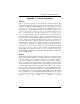
Interface Options
Due to the versatility of the OMG-ISO-COMM series a wide range of interface
configuration options are available to the end user. Please use this section as a
guide in configuring your board to provide the interface you require.
RS-232
To configure the board as RS-232 insure that the 75174 driver at U33 & U27 and
the DIP resistor pack at RP15 have been removed (if previously installed). By
installing the MAX234 driver at U34 & U28, the board will be configured as RS-
232. Please note that on two port versions of the OMG-ISO-COMM series only
one driver chip will be provided at either U33 or U34.
RS-422
To configure the OMG-ISO-COMM as RS-422 insure that the MAX234 driver at
U34 & U28 have been removed (if previously installed). By installing the 75174
driver at U33 & U27 and installing a 100 ohm DIP resistor at RP-15, the board will
be configured as RS-422. Please note that on two port versions of the OMG-ISO-
COMM series only one driver chip will be provided at either U33 or U34.
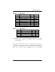
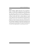
Combined RS-232 and RS-422
On the four port OMG-ISO-COMM boards two ports of RS-232 and two ports of
RS-422 is possible, but it is complicated to configure. The configuration requires
that you selectively bend (or float) pins on the DIP-resistor pack out of the
socket.
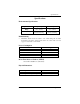
Configuration Drivers RP-15 Pin Positions
Ports 1 & 2 RS-232
Ports 3 & 4 RS-422
U34 & U27 Installed
U33 & U28 Removed
Pins 1, 7, 8, 4 "Floated"
All Others Installed
Ports 1 & 2 RS-422
Ports 3 & 4 RS-232
U33 & U28 Installed
U34 & U27 Removed
Pins 2, 3, 5, 6 "Floated"
All Others Installed
Figure 9 - Four Port RS-232/RS-422 Configuration Table