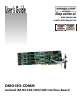
User’s Guide Shop online at www.omega.com e-mail: info@omega.
OMEGAnet ® Online Service www.omega.com Internet e-mail info@omega.com Servicing North America: USA: ISO 9001 Certified Canada: One Omega Drive, P.O. Box 4047 Stamford CT 06907-0047 TEL: (203) 359-1660 e-mail: info@omega.com 976 Bergar Laval (Quebec) H7L 5A1, Canada TEL: (514) 856-6928 e-mail: info@omega.
Contents INTRODUCTION..........................................................................1 OVERVIEW................................................................................................ 1 W HAT ’S INCLUDED ................................................................................ 1 FACTORY DEFAULT SETTINGS ............................................................ 1 CARD SETUP ..............................................................................2 A DDRESS SELECTION.........
RS-485.................................................................................................... 16 APPENDIX D - ASYNCHRONOUS COMMUNICATIONS ...............17 APPENDIX E - SILK-SCREEN ....................................................19 APPENDIX F - COMPLIANCE NOTICES ...................................20 FEDERAL COMMUNICATIONS COMMISSION STATEMENT ............ 20 EMC DIRECTIVE STATEMENT ...........................................................
Introduction Introduction Overview The OMG-ISO-COMM provides the PC with additional ground isolated serial ports for terminals, modems, printers, etc. Isolation is important in installations where the equipment being connected to the PC is either far from the PC, or on a different power transformer circuit. Ground loop current is a commonly neglected and misunderstood phenomena that leads to the failure (and destruction) of communication interfaces.
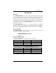
Card Setup Card Setup The OMG-ISO-COMM contains several jumper straps which must be set for proper operation. Address Selection Each port on the OMG-ISO-COMM occupies 8 consecutive I/O locations. A DIP-switch is used to set the base address for these locations. Be careful when selecting the base address as some selections conflict with existing ports. The following table shows several examples that typically do not cause a conflict.
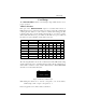
Card Setup Port Enable / Disable Each port on the OMG-ISO-COMM can be enabled or disabled with switch position 8 on the DIP-switch. The port is enabled with the switch ‘On’ or ‘Closed’ and disabled when ‘Off’ or ‘Open’. If any port is disabled, be sure to disable the interrupt request for that port by removing the IRQ jumper. IRQ Selection Headers E1, E2, E3 and E4 select the IRQ for each serial port. If COM1: is selected, this jumper must be on the IRQ4 setting.
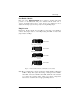
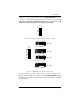
Card Setup Interrupt Mode Options Header E5 selects the interrupt mode for each port. Each port must be set in the correct mode to insure proper installation. ‘N’ indicates the (N)ormal, single interrupt per port mode. ‘S’ Indicates the (S)hared interrupt mode, which allows more than one port to access a single IRQ. Any two or more ports can share a common IRQ by placing the jumpers on the same IRQ setting, and setting the appropriate selections at E5. Consult your particular software for IRQ selection.
Card Setup Set jumper to ‘S’ if you are using more than one OMG-ISO-COMM in a bus or you wish to completely remove the pull-down resistor for hardware compatibility. Setting the board in this configuration when it is not accompanied by a pulldown resistor will prevent the ports from triggering an interrupt.
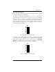
Card Setup Headers E8 and E9 RS-485 is backwardly compatible with RS-422, however it is optimized for partyline or multi-drop applications. The output of the RS-422/485 driver is capable of being active (enabled) or tri-state (disabled). This capability allows multiple PCs to be connected in a multi-drop bus and selectively polled. Halfduplex two-wire operation is also possible by connecting TX+ to RX+ and TX- to RX- in your cable hood.
Card Setup Interface Options Due to the versatility of the OMG-ISO-COMM series a wide range of interface configuration options are available to the end user. Please use this section as a guide in configuring your board to provide the interface you require. RS-232 To configure the board as RS-232 insure that the 75174 driver at U33 & U27 and the DIP resistor pack at RP15 have been removed (if previously installed). By installing the MAX234 driver at U34 & U28, the board will be configured as RS232.
Installation Installation Operating System Installation For Windows Users Start by choosing Install Software at the beginning of the CD. Choose Asynchronous COM: Port Software, SeaCOM. Other Operating Systems Refer to the appropriate section of the Serial Utilities Software. System Installation The OMG-ISO-COMM can be installed in any of the PC expansion slots, but to access the ‘AT’ or (E)ISA IRQs (10, 11, 12, 15) the adapter must be installed in one of the 16 bit slots.
Technical Description Technical Description The OMG-ISO-COMM provides the PC with two or four additional ground isolated RS-422/485/232 or two or four non-isolated RS-422/485 serial ports for terminals, modems, printers, etc. Isolation is important in installations where the equipment being connected to the PC is either far from the PC, or on a different power transformer circuit.
Technical Description Connector Pin Assignments RS-422 (DB 9 Male) Signal GND TX + TXRTS+ RTSRX+ RXCTS+ CTS- RS-232 Name Ground Transmit Data Positive Transmit Data Negative Request To Send Positive Request To Send Negative Receive Data Positive Receive Data Negative Clear To Send Positive Clear To Send Negative Pin # 5 4 3 6 7 1 2 9 8 Mode Output Output Output Output Input Input Input Input (DB 9 Male) Signal GND TD RTS RD CTS Name Ground Transmit Data Request To Send Receive Data Clear To Send P
Specifications Specifications Environmental Specifications Specification Temperature Range Humidity Range Operating 0º to 50º C (32º to 122º F ) 10 to 90% R.H. Non-Condensing Storage -20º to 70º C (-4º to 158º F) 10 to 90% R.H. Non-Condensing Manufacturing • All Printed Circuit boards are built to U.L. 94V0 rating and are 100% electrically tested. These printed circuit boards are solder mask over bare copper or solder mask over tin nickel.
Appendix A - Troubleshooting Appendix A - Troubleshooting Serial Utility test software is supplied with the adapter and will be used in the troubleshooting procedures. By using this software and following these simple steps, most common problems can be eliminated without the need to call Technical Support. 1. Identify all I/O adapters currently installed in your system. This includes your on-board serial ports, controller cards, sound cards etc.
Appendix A - Troubleshooting 8. The following are known I/O conflicts: • • • • • • The 278 and 378 settings may conflict with your printer I/O adapter. 3B0 cannot be used if a Monochrome adapter is installed. 3F8-3FF is typically reserved for COM1: 2F8-2FF is typically reserved for COM2: 3E8-3EF is typically reserved for COM3: 2E8-2EF is typically reserved for COM4: 9. Remember to use diagnostic software when troubleshooting a problem.
Appendix B - How To Get Assistance Appendix B - How To Get Assistance Please refer to Troubleshooting Guide prior to calling Technical Support. 1. Begin by reading through the Trouble Shooting Guide in Appendix A. If assistance is still needed please see below. 2. When calling for technical assistance, please have your user manual and current adapter settings. If possible, please have the adapter installed in a computer ready to run diagnostics. 3.
Appendix C - Electrical Interface Appendix C - Electrical Interface RS-232 Quite possibly the most widely used communication standard is RS-232. This implementation has been defined and revised several times and is often referred to as RS-232 or EIA/TIA-232. The IBM PC computer defined the RS-232 port on a 9 pin D sub connector and subsequently the EIA/TIA approved this implementation as the EIA/TIA-574 standard.
Appendix C - Electrical Interface RS-485 RS-485 is backwardly compatible with RS-422; however, it is optimized for partyline or multi-drop applications. The output of the RS-422/485 driver is capable of being Active (enabled) or Tri-State (disabled). This capability allows multiple ports to be connected in a multi-drop bus and selectively polled. RS-485 allows cable lengths up to 4000 feet and data rates up to 10 Megabits per second. The signal levels for RS-485 are the same as those defined by RS-422.
Appendix D - Asynchronous Communications Appendix D - Asynchronous Communications Serial data communications implies that individual bits of a character are transmitted consecutively to a receiver that assembles the bits back into a character. Data rate, error checking, handshaking, and character framing (start/stop bits) are pre-defined and must correspond at both the transmitting and receiving ends.
Appendix D - Asynchronous Communications Because each bit in asynchronous communications is sent consecutively, it is easy to generalize asynchronous communications by stating that each character is wrapped (framed) by pre-defined bits to mark the beginning and end of the serial transmission of the character. The data rate and communication parameters for asynchronous communications have to be the same at both the transmitting and receiving ends.
Appendix E - Silk-Screen Appendix E - Silk-Screen 4.2" 13.33" 3.
Appendix G - Compliance Notices Appendix G - Compliance Notices Federal Communications Commission Statement FCC - This equipment has been tested and found to comply with the limits for Class A digital device, pursuant to Part 15 of the FCC Rules. These limits are designed to provide reasonable protection against harmful interference when the equipment is operated in a commercial environment.
WARRANTY/DISCLAIMER OMEGA ENGINEERING, INC. warrants this unit to be free of defects in materials and workmanship for a period of 13 months from date of purchase. OMEGA’s WARRANTY adds an additional one (1) month grace period to the normal one (1) year product warranty to cover handling and shipping time. This ensures that OMEGA’s customers receive maximum coverage on each product. If the unit malfunctions, it must be returned to the factory for evaluation.
Where Do I Find Everything I Need for Process Measurement and Control? OMEGA…Of Course! Shop online at www.omega.