
Technical data

Expert Functions
5.2 Extending a PROFIdrive message frame
Connection of the SINAMICS S120 to the Technology CPU
Product Information, 09/2011, A5E00480378-04
135
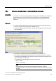
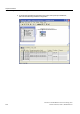
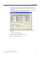
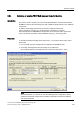
8. Switch to the "Details" tab and note the assignment of the PROFIBUS input/output
addresses. Each object of the configuration has its own area that is concluded with an
axis separator.
In this example, the selection of the two standard message frames starting at slot 10
creates the input/output area for the TB30 and the control unit.
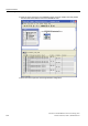
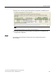
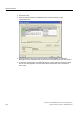
9. Note for the subsequent steps the start addresses of the objects. In our example,
these are:
– Object 3 - TB30 - Address 296
– Object 4 - Control Unit - Address 300
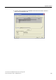
10. Accept the suggested I/O addresses for both objects.
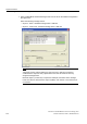
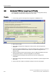
11. Click "OK" to close the configuration.