Connection of the SINAMICS S120 to ___________________ Definitions and warnings the Technology CPU SIMATIC S7-300 Connection of the SINAMICS S120 to the Technology CPU Product Information 09/2011 A5E00480378-04 SINAMICS S120 2 ___________________ automation components 3 ___________________ Commissioning 4 ___________________ Basic functions 5 ___________________ Expert Functions Safety Integrated Functions 6 ___________________ in SINAMICS Drive Systems
Legal information Legal information Warning notice system This manual contains notices you have to observe in order to ensure your personal safety, as well as to prevent damage to property. The notices referring to your personal safety are highlighted in the manual by a safety alert symbol, notices referring only to property damage have no safety alert symbol. These notices shown below are graded according to the degree of danger.
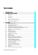
Table of contents 1 Definitions and warnings............................................................................................................................ 7 2 SINAMICS S120 automation components ................................................................................................. 9 3 2.1 System overview ............................................................................................................................9 2.2 Control unit...............................
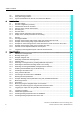
Table of contents 3.8 3.8.1 3.8.2 4 5 Creating the user program .......................................................................................................... 91 Using technology functions ......................................................................................................... 91 Special considerations for the use of an Active Line Module ..................................................... 91 Basic functions..................................................................
Table of contents 6 Safety Integrated Functions in SINAMICS Drive Systems ..................................................................... 183 6.1 Safety Integrated Functions - Overview.....................................................................................183 6.2 Safety Integrated functions in SINAMICS S120 drive systems .................................................184 6.3 6.3.1 6.3.2 6.3.3 6.3.4 6.3.5 Support of SINAMICS Safety Integrated functions by the T(F)-CPU ............
Table of contents Connection of the SINAMICS S120 to the Technology CPU 6 Product Information, 09/2011, A5E00480378-04
Definitions and warnings 1 Purpose of document This document presents the most important standard options to use the SINAMICS S120 drive system on the CPU 31xT-2 DP Technology CPU. Other functions can definitely also run together with SINAMICS S120, but they must be considered individually. Document scope ● CPU 31xT(F) as of V2.7/5.1.5 ● SINAMICS S120 as of V2.6.2 ● S7 Technology as of V4.
Definitions and warnings Connection of the SINAMICS S120 to the Technology CPU 8 Product Information, 09/2011, A5E00480378-04
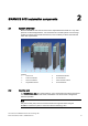
SINAMICS S120 automation components 2.1 2 System overview Because SINAMICS S120 can be used to solve sophisticated drive tasks for a very wide spectrum of industrial applications, it is constructed as a modular system. From the large number of matched components and functions, users combine just those units that best match their requirements. Legend: 2.
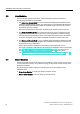
SINAMICS S120 automation components 2.3 Line Modules 2.3 Line Modules The Line Modules perform the function of the central energy infeed for the DC link. The following Line Modules are available: ● The Active Line Module (ALM) is a self-controlled infeed/regenerative feedback unit for creating a regulated DC link voltage. This decouples the connected Motor Modules from the supply voltage and fluctuations within the permitted supply tolerances do not have any effect on the motor voltage.
SINAMICS S120 automation components 2.5 Expansion and system components 2.5 Expansion and system components Expansion and system components can be used to expand the SINAMICS S120 base system so that it can perform functions directly in the drive system, record encoder signals, etc. Components For example, the following components are available for SINAMICS S120: ● The Terminal Board TB30 can be used to expand the CU320 control unit with additional digital and analog inputs/outputs.
SINAMICS S120 automation components 2.6 Determining the firmware version number Determining the firmware version of the SINAMICS S120 in S7T Config If a current configuration of the SINAMICS S120 is available in S7T Config, the firmware of the SINAMICS S120 can be determined as follows. Select in the project navigator for S7T Config the appropriate SINAMICS S120. Double-click "Overview". Open the Version overview tab. Take the firmware version of the SINAMICS S120 from this table.
SINAMICS S120 automation components 2.7 SINAMICS Support Packages 2.7 SINAMICS Support Packages Definition of the SINAMICS Support Package S7 Technology features the integrated STARTER commissioning tool which supports the use of SINAMICS Support Packages (SSP) as of V4.1 SP2. This allows users to make new drive firmware versions known to an existing STARTER/S7-Technology version without having to carry out a new installation and without the drive being actually available.
SINAMICS S120 automation components 2.7 SINAMICS Support Packages Installation All SSPs released for a product version can be installed in any order. Do not run STARTER/S7 Technology during SSP installation. To install a new SSP from CD, follow these steps: 1. Place the SSP CD into the CD drive of your programming device/PC, or save and unpack the SSP you downloaded from Product Support. 2. Select and run setup.exe in Windows Explorer 3.
3 Commissioning 3.1 Commissioning procedure Operational sequence The commissioning procedure is divided into two parts: 1. Create a STEP 7 project and make the settings of the technology CPU for the connected hardware using the HW Config and S7T Config programs. Special attention is placed on the parameterizations that must be performed both in the technology CPU and in the SINAMICS S120. 2. Parameterize SINAMICS S120, create drives and axes.
Commissioning 3.2 Connecting hardware components Setting of a fixed PROFIBUS address on the SINAMICS S120 In general, for the operation of the SINAMICS S120 together with the Technology CPU, the setting of a fixed PROFIBUS address using the DIP or rotary switches directly on the SINAMICS S120 is recommended. When the values 0 or 127 are set, the PROFIBUS address set in the p0918 parameter will be is used for the communication.
Commissioning 3.2 Connecting hardware components 3.2.2 Interconnection of the DRIVE-CLiQ components System overview The SINAMICS S120 components are connected with each other using an integrated bus system, the DRIVE-CLiQ. Not only can be the individual modules of the drive system, such as Line Modules and Motor Modules, connected with the Control Unit, but also motor encoders or external encoders can be connected with the Motor Modules.
Commissioning 3.2 Connecting hardware components Rules for the interconnection of DRIVE-CLiQ components To work with DRIVE-CLiQ technology and to use technology functions, e.g. the automatic topology recognition, certain rules must be followed for the commissioning of the SINAMICS S120 drive system.
Commissioning 3.2 Connecting hardware components Recommended DRIVE-CLiQ rules When the recommended rules for DRIVE-CLiQ wiring are observed, the components will be automatically assigned to the drives during online configuration or during topology recognition. Note Complete, detailed information about these rules is contained in the documentation for the SINAMICS S120 drive system available on the Internet (http://apps01.industry.siemens.com/content/00000100/Content/syn_s120.aspx?rc=1).
Commissioning 3.
Commissioning 3.2 Connecting hardware components 3.2.3 Additional hardware wiring for Smart Line Modules without DRIVE-CLiQ For Smart Line Modules without a DRIVE-CLiQ interface, the signals of these modules must be connected through hardware wiring with the CU320 control unit. The following signals must be wired between the Smart Line Module (SLM) and the CU320 control unit. Signal SLM TB30 Comment SLM Ready DO: X21.1 ⇨ DI: X481.1 SLM operational Overtemperature Prewarning DO: X21.
Commissioning 3.2 Connecting hardware components 3.2.4 Special features of the SINAMICS S120 Training Case Basic procedure The devices are designed for use with the 230 V AC power supply, so you must change the setting for the device connection voltage of the motor modules if you are using the SINAMICS S120 Training Case. To change the setting, follow these steps: 1. Select the respective drive in S7T Config. 2. In the context menu, select the Experts > Expert List command. 3.
Commissioning 3.3 Preparing the connection to the SINAMICS 3.3 Preparing the connection to the SINAMICS 3.3.1 Overview Introduction To establish a connection for the configuring of the SINAMICS S120 between the programming device and the drive system, several preliminary tasks must be performed; these tasks are discussed in detail in the following sections. 3.3.
Commissioning 3.3 Preparing the connection to the SINAMICS 3.3.3 Configuring in HW Config Introduction Now double-click the "Hardware" element to configure the hardware of the SIMATIC 300 station using the HW Config tool. Technology CPU: configuring the hardware 1. Select the "SIMATIC Technology CPU" hardware catalog and add there a mounting rail with drag-and-drop to the configuration. 2. Then give the mounting rail at slot 1 a power supply, e.g. PS 307 2A, the mounting rail at slot 2 a CPU, e.g.
Commissioning 3.3 Preparing the connection to the SINAMICS Technology CPU: Configuring PROFIBUS DP (DRIVE) 1. After selecting the Technology CPU, the "Properties - PROFIBUS interface DP(DRIVE) (R0/S3.1)" dialog box will be displayed. Click the "New" button to create a new PROFIBUS network there. 2.
Commissioning 3.3 Preparing the connection to the SINAMICS 3. Click the "Options" button to make additional settings for PROFIBUS. In the "Constant bus cycle time" tab, activate the "Activate constant bus cycle time" function. Also activate the "Slave Synchronization" to keep the time values identical for all connected slaves. Then click the "Recalculate" button to calculate the constant DP cycle time and the Ti and To times. Round up the calculated constant DP cycle time (0.
Commissioning 3.3 Preparing the connection to the SINAMICS Technology CPU: configuring the MPI interface The X1-MPI/DP interface of the CPU is set by default to MPI communication with 187.5 KBit/s and to "not networked". To access the Technology CPU and the SINAMICS S120, the transmission rate of the interface should be set to the highest transmission rate supported by the programming device, for example 12 Mbps.
Commissioning 3.3 Preparing the connection to the SINAMICS SINAMICS S120: configuring the hardware 1. In HW Config, insert a SINAMICS S120 drive on PROFIBUS-DP (DRIVE). To do this, select a SINAMICS S120 in the hardware catalog under "SIMATIC-Technology \PROFIBUS DP (DRIVE) \Drives\SINAMICS". 2. In the "Properties" dialog, assign a PROFIBUS address (for example 4) and set the device version to the current firmware version of the SINAMICS S120. Note The device version cannot be changed later in HW Config.
Commissioning 3.3 Preparing the connection to the SINAMICS 4. In the "Isochronous operation" tab, activate isochronous operation for this slave. Then click the "Align" button to perform the isochronous alignment of the slave with the Technology CPU. 5. Click "OK" to accept the settings. Saving and compiling the project Save and compile the hardware configuration and load the project into the attached Technology CPU.
Commissioning 3.3 Preparing the connection to the SINAMICS 3.3.4 Activating routing in NetPro Introduction To establish an online connection between the programming device and the SINAMICS S120 drive system, the "Routing of a SIMATIC PC station" in NetPro must be activated. This is necessary because the programming device is connected via the X1-MPI/DP interface to the technology CPU and to the SINAMICS S120 on the PROFIBUS DP (DRIVE) of the Technology CPU.
Commissioning 3.3 Preparing the connection to the SINAMICS Procedure To enable routing for the programming device, follow these steps: 1. Open the NetPro program in the SIMATIC Manager with the menu command Options > Configure Network. 2. Add a PG/PC station from the "Network objects" catalog from the "Stations" directory. Note If the SINAMICS S120 is not displayed in NetPro, switch in the View menu to the "With DP Slave / IO Devices" display. 3.
Commissioning 3.3 Preparing the connection to the SINAMICS 5. As PROFIBUS address, set the address "0" for the PG (recommended default address). Click the "OK" button to confirm the setting. 6. In the "Assignment" tab, assign the MPI interface of your programming device to the interface module of the PG/PC. Select the MPI interface in the upper window and the interface module of the PG/PC in the middle window and click the "Assign" button.
Commissioning 3.3 Preparing the connection to the SINAMICS Select the "Active" check box in the "S7Online access" field. Note If the project is transferred to a different programming device, this assignment must be repeated because these settings are device-dependent.
Commissioning 3.3 Preparing the connection to the SINAMICS Result The network configuration is now completed. Once again check the MPI address settings of the PG/PC interface (address 0) and the Technology CPU (address 2) in the overview and save and compile the network configuration. Load the configuration into the target device. The successful activation of the routing function is indicated by the connection of the PG/PC interface with the MPI network having a yellow background in the overview.
Commissioning 3.4 Configuring the drive components 3.4 Configuring the drive components 3.4.1 Overview Basic procedure You configure the drive components in S7T Config. You open S7T Config by double-clicking the "SINAMICS_S120...\Commissioning" entry in the SINAMICS_S120... folder in the SIMATIC Manager.
Commissioning 3.4 Configuring the drive components Procedure 1. Use the Project > Connect to target system menu command to establish an online connection to the SINAMICS S120 in S7T Config. 2. Place the SINAMICS S120 in the initial state by restoring the factory settings. To do this, mark "SINAMICS_S120" and select the Target device > Restore factory settings menu command in the shortcut menu. Pay attention to any messages and acknowledge them. Also save the factory settings in the ROM of the drive.
Commissioning 3.4 Configuring the drive components 3. Double-click on the "Automatic configuration" entry of the SINAMICS S120 in the project navigation. 4. Click the "Configure" button to start the configuration.
Commissioning 3.4 Configuring the drive components 5. Select the type of the drive object. In this example, a servo type drive is to be configured. To configure the individual drives differently, the type for each drive can be selected separately in the lower part of the dialog box. Click the "Create" button to confirm the settings. Result The configuration is created and will be loaded to the programming device. Switch to offline mode. This completes the automatic configuration of the drive system.
Commissioning 3.4 Configuring the drive components 3.4.3 Manual configuring Introduction The manual configuring can only be performed in offline mode of S7T Config. The components of the drive system that are present must be configured manually using S7T Config. Various infeed modules of the SINAMICS The procedure to be adopted for the manual configuring depends on the SINAMICS infeed.
Commissioning 3.4 Configuring the drive components Configuring with Active Line Module (ALM) 1. In S7T Config, open the SINAMICS S120_CU320 folder, and double-click the "Configure drive unit" entry or the drive. 2. First create the control unit, and the option modules. If you are using the TB30 terminal board, select it from the drop-down list, and click the "Next" button to confirm the setting.
Commissioning 3.4 Configuring the drive components 3. For the selection of the SINAMICS infeed, you can choose between modules with or without DRIVE-CLiQ connection. Select "Yes" for the active line module, then click "Next" to confirm the setting.
Commissioning 3.4 Configuring the drive components 4. In the next dialog, select "Active infeed" for the active line module, and click "Next" to confirm the setting.
Commissioning 3.4 Configuring the drive components 5. Then select the appropriate module from the list and click the "Next" button to accept the other settings without change.
Commissioning 3.4 Configuring the drive components 6. Check the settings for the line/DC link identification, line filter, voltage sensing module, and braking module, and adapt them to your application, if necessary. Click the "Next" button to confirm the settings.
Commissioning 3.4 Configuring the drive components 7. For the process data communiction between the Technology CPU and the infeed, select the "SIEMENS message frame 370 for the infeed". Click "Next" to confirm the setting.
Commissioning 3.4 Configuring the drive components 8. Now start the configuration of the drive by selecting "Yes" and clicking the "Next" button to confirm the setting.
Commissioning 3.4 Configuring the drive components 9. Enter the name of the drive "Drive_1" in the "Drive properties" dialog. 10.Select the "Servo" type on the "General" tab. Select the "Drive object no." tab. Enter a drive object number. Click the "Next" button to confirm the settings. Note If you want to set a different operating mode later, you have to reconfigure the drive.
Commissioning 3.4 Configuring the drive components 11.Select "Speed control (with encoder)" as the control method, and click "Next" to confirm the setting.
Commissioning 3.4 Configuring the drive components 12.Select the appropriate power section component from the list, and click "Next" to confirm the setting.
Commissioning 3.4 Configuring the drive components 13.If you have configured a Double Motor Module, you must now select the power unit connection of the motor on the module. For the first motor, select, for example, the Connection X1. Click "Next" to confirm the setting.
Commissioning 3.4 Configuring the drive components 14.Select the connected motor. If a motor with a DRIVE-CLiQ interface is used, select this setting. The motor data is then read from the electronic nameplate of the motor via the DRIVE-CLiQ connection. Alternatively, you can select the (standard) motor from a list, or enter the motor data directly. Then click "Next" to confirm the setting.
Commissioning 3.4 Configuring the drive components 15.Configure the motor holding brake, if there is one, and click "Next" to confirm the setting. For motor holding brakes which are a direct component of the motor block, use the "Motor holding brake acc. to sequential control" setting. For externally fitted motor holding brakes, select the "Motor holding brake acc. to sequential control, brake connection via BICO interconnection" setting, and also link it to a free output.
Commissioning 3.4 Configuring the drive components 16.If you did not activate encoder sensing via the Drive CLiQ interface, you can select the relevant encoder from the list box. Select the desired encoder and the encoder evaluation, then click "Next" to confirm the setting.
Commissioning 3.4 Configuring the drive components 17.For process data communication between the Technology CPU and power section via PROFIBUS DP (DRIVE), set a suitable message frame, such as message frame 105. You can find further information about the properties of the individual message frames in the "Extending a PROFIdrive message frame (Page 130)" chapter. Click "Next" to confirm the setting.
Commissioning 3.4 Configuring the drive components This completes the configuration. You can review your parameter settings again in the summary; click the "Finish" button to close the configuration. 18.Then repeat the configuration for any other motors connected to the drive system.
Commissioning 3.4 Configuring the drive components Configuring with Smart Line Module (SLM) 1. In S7T Config, open the SINAMICS S120_CU320 folder, and double-click the "Configure drive unit" entry or the drive. 2. Insert the control unit and optionally the add-on modules, for example TB30 terminal board. Select the desired values and click "Next" to confirm the settings. 3. For the selection of the SINAMICS infeed, you can choose between modules with or without DRIVE-CLiQ connection.
Commissioning 3.4 Configuring the drive components 4. Start the configuration of the drive by selecting "Yes" and clicking the "Next" button to confirm the setting.
Commissioning 3.4 Configuring the drive components 5. Enter the name of the drive "Drive_1" in the "Drive properties" dialog. Select the "Servo" type on the "General" tab. Select the "Drive object no." tab. Enter a drive object number. Click the "Next" button to confirm the settings. Note If you subsequently want to change the drive object type, you will have to reconfigure the drive.
Commissioning 3.4 Configuring the drive components 6. Select "Speed control (with encoder)" as the control method, and click "Next" to confirm the setting.
Commissioning 3.4 Configuring the drive components 7. Select the appropriate power section component from the list, and click "Next" to confirm the setting.
Commissioning 3.4 Configuring the drive components 8. For Smart Line Modules without DRIVE-CLiQ interface, a message appears with information on the hardware wiring of the ready signals between infeed and the drive. Read this information and confirm the message with "OK". Note For SLM without DRIVE-CLIQ, the hardware wiring of the ready signal for the infeed can take place either via the digital inputs of the CU 320 control unit or via the additional digital inputs of the TB 30 terminal board.
Commissioning 3.4 Configuring the drive components 9. Now perform the internal wiring of the Ready to run signal using the BICO engineering of the SINAMICS S120. Click the blue icon for the wiring of the binector and select "Control unit" or "Further interconnections". The dialog for the possible interconnections of the individual components opens. Select, for example, the "r722 Bit0 CO/BO parameter here: CU digital inputs, status: DI 0 X122.1….
Commissioning 3.4 Configuring the drive components 10.If you have configured a Double Motor Module, you must now select the power unit connection of the motor on the module. For the first motor, select the X1 connection, for example. Click the "Next" button to confirm the setting.
Commissioning 3.4 Configuring the drive components 11.Select the connected motor. If a motor with a DRIVE-CLiQ interface is used, select this setting. The motor data is then read from the electronic nameplate of the motor via the DRIVE-CLiQ connection. Alternatively, you can select the (standard) motor from a list, or enter the motor data directly. Then click "Next" to confirm the setting.
Commissioning 3.4 Configuring the drive components 12.Configure the motor holding brake, if there is one, and click "Next" to confirm the setting. For motor holding brakes which are a direct component of the motor block, use the "Motor holding brake with sequential control" setting. For externally fitted motor holding brakes, select the "Motor holding brake acc. to sequential control, brake connection via BICO interconnection" setting, and also link it to a free output.
Commissioning 3.4 Configuring the drive components 13.If you did not activate encoder sensing via the Drive CLiQ interface, you can select the relevant encoder from the list box. Select the desired encoder and the encoder evaluation, then click "Next" to confirm the setting.
Commissioning 3.4 Configuring the drive components 14.For process data communication between the Technology CPU and power section via PROFIBUS DP (DRIVE), set a suitable message frame, such as message frame 105. You can find further information about the properties of the individual message frames in the "Extending a PROFIdrive message frame (Page 130)" section. Click "Next" to confirm the setting.
Commissioning 3.4 Configuring the drive components 15.This completes the configuration. You can review your parameter settings again in the summary; click the "Finish" button to close the configuration. 16.Then repeat the configuration for any other motors connected to the drive system.
Commissioning 3.4 Configuring the drive components 3.4.4 Alignment of the PROFIdrive message frames Introduction To configure the PROFIBUS communications interface, the message frame configuration in S7T Config and in HW Config must be aligned. Among other things, this alignment determines the I/O addresses for the PROFIdrive data communiction between SINAMICS and the Technology CPU. Alignment with an Active Line Module (ALM) To perform the alignment, open the "S120_CU320" folder in S7T Config.
Commissioning 3.4 Configuring the drive components Alignment with a Smart Line Module (SLM) To perform the alignment, open the message frame configuration in S7T Config (same as for the ALM), and check and correct the order of the individual components there. To do this, select the relevant component, and use the arrow buttons to move it up or down. The objects must be kept in the following order: 1. Drives 2. Option modules 3.
Commissioning 3.4 Configuring the drive components 3.4.6 Optimizing the speed controller in the drive Introduction The controllers in the drive must be working optimally to ensure that systems are not susceptible to faults. There are tools for automatically optimizing the controller in SINAMICS firmware version V2.5 and S7 Technology V4.1 or later.
Commissioning 3.4 Configuring the drive components Procedure 1. Switch to online mode. 2. In the navigator, select the drive to be optimized, then switch to the \Commissioning\Automatic controller setting sub-folder. 3. Set the T-CPU to STOP mode. 4. Obtain control priority by pressing the "Get control priority!" button in the automatic controller setting dialog. 5. Switch on the drive by clicking "Drive ON" in the automatic controller setting dialog.
Commissioning 3.4 Configuring the drive components 6. Carry out the four steps in automatic mode, or carry out the individual steps using the operating buttons in the automatic controller setting dialog. The controller optimization results will be displayed.
Commissioning 3.4 Configuring the drive components 7. Transfer the calculated speed controller parameter values to the drive by clicking "Accept" in the automatic controller setting dialog. 8. Switch off the drive by clicking "Drive OFF" in the automatic controller setting dialog. 9. Give up control priority by pressing the "Get control priority!" again in the automatic controller setting. 10.Set the T-CPU back to RUN mode. 11.Start a "Copy RAM to ROM" operation for the drive you have just optimized. 12.
Commissioning 3.5 Diagnosing the SINAMICS configuration 3.5 Diagnosing the SINAMICS configuration Once the configuring for the SINAMICS S120 has been completed, the topology of the DRIVE-CLiQ wiring can be checked in online mode and the drive moved using the SINAMICS S120 control panel. 3.5.1 Checking the DRIVE-CLiQ wiring online Procedure To check the DRIVE-CliQ wiring online, follow these steps: 1. Set S7T Config to online mode. 2. Open the "S120_CU320" folder. 3. Select the "Topology" command.
Commissioning 3.5 Diagnosing the SINAMICS configuration 3.5.2 Drive test using the SINAMICS control panel Introduction After the successful configuring of the SINAMICS S120 drive system, the drives can be controlled and moved in speed-controlled operation using the drive control panel in S7T Config. Assuming control priority Open the "S120_CU320" folder in S7T Config. Select the Drives > Drive_1 > Commissioning > Control Panel command. Select there the drive that is to be tested.
Commissioning 3.5 Diagnosing the SINAMICS configuration Operation using the drive control panel Activate the "Enables" option box and operate the drive control panel using the keys described below: Button Function Enable the infeed for an Active Line Module or for a Basic Line Module using DRIVE-CLiQ. Starting the motion. A speed setpoint for the axis can be specified in the Setpoint input box. Stopping the motion.
Commissioning 3.6 Creating technology objects 3.6 Creating technology objects 3.6.1 Creating and configuring axes Introduction Once the SINAMICS S120 drive system has been configured and placed in operation, the axes must now be created in the technology section of the Technology CPU. This gives the CPU the access to and the control of the axes. Procedure 1. Open the Technology folder in S7T Config and double-click on the "Insert axis" function to add an "axis" technology object.
Commissioning 3.6 Creating technology objects 2. Enter in the first dialog box a name for the axis and select the required axis technology. Click on the "OK" button to confirm your entry. Note The axis technology can no longer be changed once it has been selected. If a different axis technology is to be selected, the technology object must be recreated.
Commissioning 3.6 Creating technology objects 3. Select "Linear, Electric" as the axis type used. Select "Configure units" if needed and click "Next" to confirm the setting.
Commissioning 3.6 Creating technology objects 4. The axis is now assigned to the drive of the SINAMICS S120. If the SINAMICS S120 is not yet available in the list of drive devices, click the "Set up addresses" button. A free drive of the selected drive device can be selected from the list for the assignment. The message frame (e.g. message frame 105) required for the communication between the Technology CPU and the drive system will be fetched automatically from the drive configuration. 5.
Commissioning 3.6 Creating technology objects 7. Select the encoder type, the encoder mode and the measuring system to be connected to the selected drive. Again, click the "Data transfer from the drive" button to automatically accept the data configured in the drive.
Commissioning 3.6 Creating technology objects 8. Enter the encoder-specific data, for example, encoder pulses per revolution and fine resolution. Additional information on this data can be obtained in the chapter "Encoder settings" (Page 93)". If you have transferred the encoder data using the "Data transfer from the drive" button, the encoder-specific data will already be preset correctly. You can then immediately confirm the dialog with "Next".
Commissioning 3.6 Creating technology objects 9. At the end of the configuration, you can once again check the entered data in the overview before you click the "Finish" button to close the configuration. Also create the technology objects for all other axes of the SINAMICS S120 drive system and then close S7T Config.
Commissioning 3.6 Creating technology objects 3.6.2 Technology Objects Management (TOM) Procedure 1. Double-click the "Technology objects" entry in the "Technology" folder of the SIMATIC station to open the Technology Objects Management (TOM) in the SIMATIC Manager. 2.
Commissioning 3.6 Creating technology objects The created technology data blocks are displayed in the list of the technology data blocks in the module folder. The Technology Objects Management program can then be closed. Result The created technology data blocks are now also in the SIMATIC Manager in the "Blocks" folder of the SIMATIC 300 station. The icons of the data blocks are derived from the designations of the technology objects in S7T Config.
Commissioning 3.7 Diagnosing the technology configuration 3.7 Diagnosing the technology configuration 3.7.1 Overview Introduction The configuration of the "Axes" technology objects in S7T Config can also be checked using the axis control panel in S7T Config. The motion commands can be specified directly for the technology objects and thus the successful linking of the technology objects with the drives. 3.7.
Commissioning 3.7 Diagnosing the technology configuration Enabling the infeed for a Smart Line Module The ready signal is used to enable a Smart Line Module without DRIVE-CLiQ interface. As shown in the chapter "Manual configuring" (Page 39), Configuration with Smart Line Modules (SLM)", this was connected when you configured the Smart Line Module. Ensure that the ready signal has logical value 1 in order to enable the Smart Line Module.
Commissioning 3.7 Diagnosing the technology configuration 3.7.3 Axis test using the technology axis control panel Procedure Once the drive infeed is active, the axis control panel can be used to operate the axes. The axis control panel buttons can be used to invoke the following functions: Button Function Set axis enable.
Commissioning 3.7 Diagnosing the technology configuration Depending on the selected operating mode of the axis, various parameters for the axis motion can be specified in an additional input window.
Commissioning 3.8 Creating the user program 3.8 Creating the user program 3.8.1 Using technology functions The user program is used to trigger the axes in cyclic operation of the Technology CPU. Technology functions can be used to trigger the technology objects, such as axes, output cams, external encoders, measuring probes, etc. The individual motions of the axes are programmed by calling the appropriate technology function module in the S7 user program in the correct sequence.
Commissioning 3.
Basic functions 4.1 Encoder settings 4.1.1 Encoder configuration (overview) 4 Principle The supported encoder types depend on the device. You will find more detailed information in the supplementary descriptions, or in the manuals for the SINAMICS S120 and the drives. The encoder is configured in S7T Config in two stages: 1. Set the encoder type when you configure the drive. 2. Set selected dependent encoder parameters, such as number of data bits, resolution etc. when you configure the axis. 4.1.
Basic functions 4.1 Encoder settings Cyclical actual value: Gn_XIST_1 In the "cyclical actual value" Gn_XIST_1 (n = 1 or 2, number of the encoder), the incremental change in position of the encoder is transmitted to the PLC. The drive simply evaluates the counting pulses of the encoder, and generates the "cyclical actual value" from them. As soon as the drive control unit is connected to the supply voltage, the value zero is always transmitted via the "cyclical actual value".
Basic functions 4.1 Encoder settings Example: The position value of an absolute encoder is set in the PLC as follows: 1. The PLC uses a command to request the absolute value of the encoder from the drive unit. 2. The drive unit reads the absolute value from the encoder. 3. The absolute value of the encoder is returned by the drive unit in the "absolute actual value" Gn_XIST_2 (n = 1 or 2, number of the encoder) to the PLC. 4.
Basic functions 4.1 Encoder settings Multiturn information (parameter 421 in the drive) The multiturn information contains the number of full encoder revolutions. With each complete revolution of the encoder, the multiturn information is incremented by one. If the maximum data width of the multiturn information is achieved, the encoder actual value is reset to zero. Encoder pulses per revolution (parameter 408 in the drive) The encoder pulses per revolution is the characteristic parameter of the encoder.
Basic functions 4.1 Encoder settings Fine resolution (parameter 418 / Parameter 419 in the drive) Encoders can provide much more precise information via their internal sampling mechanism (sine / cosine oscillations, sub-sampling on a etched pane of glass). These can be evaluated by the drive unit, and transferred to the PLC as a fine resolution. The encoder actual values that can be transferred from the drive to the PLC are limited to 32-bit, however.
Basic functions 4.1 Encoder settings Number of data bits When you configure an axis in S7T Config, you must specify the "number of data bits" for the encoder. The "number of data bits" corresponds to the proportion of user data of the 32-bit wide encoder actual value, and is calculated from the sum of the data bits for the encoder and multiturn resolutions. To display the position correctly, the values set in S7T Config must agree with the values configured in the drive.
Basic functions 4.1 Encoder settings 4.1.4 Encoder types Encoder type - incremental encoder Incremental encoders output the value zero after the supply voltage has been interrupted. Axes with incremental encoders must be rereferenced after each voltage interruption. Encoder type - absolute encoder Absolute encoders can also provide the absolute position value after the supply voltage of the drive control unit has been interrupted.
Basic functions 4.1 Encoder settings 4.1.5 Encoder mode Different protocols are used to transfer the encoder data between the encoder and the drive. These protocols depend on which encoder is used. The required encoder mode can be found in the technical documentation for the encoder. 4.1.6 Setting encoder parameters in the technology Procedure When you configure an axis or an external encoder, you set the encoder data in the relevant dialog fields. 1.
Basic functions 4.1 Encoder settings Enter the encoder-specific data, such as the number of encoder pulses, the number of data bits and the multiplication factors. Note If the value zero has been set for the multiplication factors, the factory settings (11-bit for Gn_XIST_1 and 9-bit for Gn_XIST_2) will be used.
Basic functions 4.1 Encoder settings 4.1.7 Display of the encoder parameters in S7T Config Display of the encoder parameters To display the encoder data, open the folder "\Technology\Axes\Axis_1" for the "axis_1" in S7T Config and double-click on "Configuration" to open the dialog box for configuration of the axis.
Basic functions 4.1 Encoder settings The "Encoder configurations" area of the "Configuration" dialog box contains the encoder settings for the axis. List of encoder parameters to be set A current list of the encoder parameters to be set is available for download on the Internet in the "Applications and Tools" area at the following address: (http://support.automation.siemens.
Basic functions 4.2 Homing 4.2 Homing 4.2.1 Homing possibilities Introduction The "Homing" function is used to align the actual value of an encoder with the position of the machine after the supply power is switched on or after the replacement of the encoder. Where as incremental encoders must be homed after each restart of the system, absolute encoders normally only need to be homed after a replacement of the encoder or the twisting of the spindle without encoder.
Basic functions 4.2 Homing Direct homing The axis position will be set without taking account of the reference cam (encoder zero mark or reference cam). If the home position is to be exactly assigned to a mechanical position, the axis must be stationary during the action. Correct position value An offset value will be subtracted from the current axis position. Any current motions and the homing will not be affected.
Basic functions 4.2 Homing Hardware configuration The homing BERO is connected to a free SIMATIC peripheral input (either to an integrated input of the Technology CPU or to a distributed input (e.g. ET 200M) on the DP(DRIVE)).
Basic functions 4.2 Homing Setting of the integrated inputs in the Technology CPU In the example shown here, the digital inputs integrated in the Technology CPU are to be used to fetch the homing output cam (BERO). The hardware address of these integrated inputs are required for the settings of the homing mode in the technology. You set these during the configuration of the Technology CPU in HW Config. In the shown example, the hardware address of the first integrated digital input is byte 66 and bit 0.
Basic functions 4.2 Homing Setting of the homing mode in the technology As next step, activate the "Homing" function and enter the address of the homing output cam. 1. To activate the "Homing" function, switch in the S7T Config project navigator to the "\Technology\Axes\Axis_2\Homing" dialog box. 2. In the "Homing" dialog box, set the homing mode to "Homing output cam and encoder zero mark".
Basic functions 4.2 Homing 3. The logical hardware address of the homing output cam (BERO) must be specified. As described above, the first integrated digital input should be used in this example. This is configured with hardware address byte 66 and bit 0. "Start of homing procedure" specifies the approach direction (counting direction) of the Bero 4. Enter appropriate values in the "Approach velocity", "Entry velocity", and "Reduced velocity" input boxes.
Basic functions 4.2 Homing Hardware configuration A typical application example is an encoder without zero mark evaluation. An external zero mark (Bero) is used in place of the encoder zero mark. To ensure short response times, it is read indirectly via the digital inputs of the CU320.
Basic functions 4.2 Homing Assignment of the equivalent zero mark signal to the digital input of the SINAMICS For homing to an external zero mark with axes on the PROFIBUS, the external zero mark must be configured as digital input on the drive. This requires that the configuration of the drive specifies which internal digital input of the CU320 is to be used to fetch the equivalent zero mark signal.
Basic functions 4.2 Homing Inverting the selected digital input of the SINAMICS A general condition in conjunction with SINAMICS governs the homing only with an external zero mark. Only negative edges are permitted for the positive travel direction and only positive edges are permitted for the negative travel direction, this means that the same cam side is always used. This means that your construction circumstances may require that the BERO signal needs to be inverted.
Basic functions 4.2 Homing Setting of the homing mode in the technology The next step is to enable the "Homing" function in the technology. 1. To activate the "Homing" function, switch in the S7T Config project navigator to the dialog: "\Technology\Axes\Axis_2\Homing". 2. In the "Homing" dialog box, set the "Homing mode" to "External zero mark only". The "Signal transition" selection boxes specify whether a rising or falling edge is to be evaluated to detect the Bero signal.
Basic functions 4.2 Homing 3. Enter appropriate values in the "Approach velocity", "Entry velocity", and "Reduced velocity" input boxes. Note Note that only negative edges are permitted for the positive travel direction, and only positive edges are permitted for the negative travel direction, which means that the same cam side is always used. This completes the configuring of the technological part of the homing function in S7T Config.
Basic functions 4.2 Homing Hardware configuration A typical application example is an encoder without zero mark evaluation. An external zero mark (Bero) is used in place of the encoder zero mark. To ensure short response times, it is read indirectly via the digital inputs of the CU320. The same signal is also evaluated via an integrated input on the Technology CPU.
Basic functions 4.2 Homing Setting of the homing mode in the technology The next step is to enable the "Homing" function in the technology. 1. To activate the "Homing" function, in the S7T Config project navigator switch to the dialog: "\Technology\Axes\Axis_2\Homing". 2. In the "Homing" dialog box, set the "Homing mode" to "External zero mark only". 3. Select "Yes" from the "Ext. zero mark signal from drive available" selection box.
Basic functions 4.2 Homing 4. In the "Ext. zero mark input" box, enter the address of the integrated inputs of the Technology CPU from HW Config, for example PI66.0. 5. Enter meaningful values in the "Approach velocity", "Entry velocity", and "Reduced velocity" input boxes. Note Note that only negative edges are permitted for the positive travel direction, and only positive edges are permitted for the negative travel direction, which means that the same cam side is always used.
Basic functions 4.2 Homing Hardware configuration A motor encoder with zero mark is connected to the SINAMICS S120. The evaluation can be made using the zero mark signal of the encoder, an additional homing output cam (Bero) is not required.
Basic functions 4.2 Homing Setting of the homing mode in the technology Because the input signal for the homing is part of the information transferred from the motor encoder, no further steps are required in the configuration of the drive. You can start immediately by activating the "Homing" function in the technology. 1. To activate the "Homing" function, switch in the S7T Config project navigator to the dialog box: "\Technology\Axes\Axis_2\Homing". 2.
Basic functions 4.2 Homing Creating the S7 user program Use the Technology Object Manager (TOM) to create a technology data block (TO-DB) assigned to the homing output cam technology object. The technology data block (TO-DB) allows the functions on the associated technology object to be executed using the provided FBs. For the homing, use the FB403 MC_Home function block in your S7 program. 4.2.
Basic functions 4.2 Homing 6. In the "Parameters" tab, set the "Absolute encoder adjustment" homing mode in the selection window. 7. In the "Options" tab, enter the absolute value encoder offset (usually the negative, current actual value) in the "Home position coordinate" input box.
Basic functions 4.3 Triggering of the integrated outputs of the CU 320 Control Unit 8. Press the button to start the absolute encoder calibration. The actual position value will be corrected with the entered offset. The displayed position of the "Axis_1" axis is now 0.0 mm. 9. Save in the project the data that has been entered online. 4.3 Triggering of the integrated outputs of the CU 320 Control Unit 4.3.
Basic functions 4.3 Triggering of the integrated outputs of the CU 320 Control Unit Creating an output cam To create a cam switch, follow these steps: 1. In the project navigator of S7T Config, switch to the "\Technology\Axes\Axis_1\Output_Cam" dialog and double-click on "Insert output cam". 2. In the "Insert output cam" dialog, you can, for example, enter a name for this output cam. 3. Click "OK" to accept the settings.
Basic functions 4.3 Triggering of the integrated outputs of the CU 320 Control Unit 4. To set the parameters for the output cam, switch to the "\Technology\Axes\Axis_1\Output_Cam\Output_Cam_1" dialog in the S7T Config project navigator. 5. Select the "Activate output" check box. 6. Enter "Hardware address 300" and "Bit number 0" from the HW Config hardware configuration. Result This completes the configuring of the output cam.
Basic functions 4.3 Triggering of the integrated outputs of the CU 320 Control Unit Linking the message frame interface of the control unit with the output terminal To link the message frame interface of the control unit with the actual output terminal, follow these steps: 1. In the S7T Config project navigator, switch to the "\SINAMICS_S120\Control_Unit\Inputs/Outputs" dialog. 2. There, go to the "Bidirectional digital inputs/outputs" tab. 3.
Basic functions 4.3 Triggering of the integrated outputs of the CU 320 Control Unit Creating the S7 user program Use the Technology Object Manager (TOM) to create a technology data block (TO-DB), which is assigned to the homing output cam technology object. The technology data block (TO-DB) allows the functions on the associated technology object to be executed using the provided FBs. For the output cam, use the FB 430 MC_CamSwitch function block in your S7 program.
5 Expert Functions 5.1 PROFIdrive message frame 5.1.1 Message frame types Selection help for the PROFIdrive message frames By default, the SINAMICS S120 is connected to the Technology CPU via PROFIBUS DP (DRIVE). Depending on the desired axis functionality, this connection can be made using various device-specific message frames. The following selection table shows the properties of the individual message types. Sign-oflife monitoring (SoLmon) 1.
Expert Functions 5.1 PROFIdrive message frame 3=' 3=' 3=' 3=' 3=' 3=' 3=' 3=' 3=' 7(/B 6HW 67: 7(/B $FWXDO =6: 7(/B 6HW 67: 162//B% 67: 7(/B $FWXDO =6: 1,67B% =6: 7(/B 6HW 67: 162//B% 67: * B 67: 7(/B $FWXDO =6: 1,67B% =6: * B =6: 7(/B 6HW 67: 162//B% 67: * B 67: 7(/B $FWXDO =6: 1,67B% =6: * B =6: H J * B;,67 H J * B;,67 7(/B 6HW 67: 162//B% 67: * B 67: ;(55 .
Expert Functions 5.1 PROFIdrive message frame 5.1.2 Example: telegram 105 Structure Telegram 105 contains the following data, where the first row of the table represents the setpoint transfer from the controller to the drive and the second row represents the actual value transfer from the drive to the controller. 7HOHJU 3=' 67: 3ODQQHG $FWXDO =6: 3=' 3=' 3=' 3=' 3=' 3=' 3=' 3=' 3=' 162//B% 67: 0B 5HG * B 67: ;(55 .
Expert Functions 5.2 Extending a PROFIdrive message frame 5.2 Extending a PROFIdrive message frame 5.2.1 Address areas Introduction The message frame types described in the "PROFIdrive message frame (Page 127)" chapter are used to transfer the drive data. Additional PROFIdrive message frames are available to establish a connection with the distributed input/outputs on PROFIBUS DP (DRIVE), with integrated inputs/outputs on the control unit, or with extensions on the Drive-CLiQ.
Expert Functions 5.2 Extending a PROFIdrive message frame 5.2.2 Extending a message frame by creating additional components Introduction For example, to make the integrated digital input/outputs of the SINAMICS S120 available to the Technology CPU, the input information must be transferred via the PROFIBUS DP (DRIVE). This requires the creation of an additional PROFIdrive message frame for the control unit.
Expert Functions 5.2 Extending a PROFIdrive message frame 5. To assign the integrated input/outputs to the control unit input/output addresses, switch to the HW Config hardware configuration.
Expert Functions 5.2 Extending a PROFIdrive message frame 6. Open the object properties of the SINAMICS S120 there and click the "Activate..." button in the "Configuration" tab.
Expert Functions 5.2 Extending a PROFIdrive message frame 7. Select a PROFIBUS standard message frame from the list for the address assignment in the object rows. Select the following message frames: – Object 3 - TB30 - Standard message frame 1 PZD 2/2 – Object 4 - Control Unit - Standard message frame 1 PZD 2/2 Note Telegrams must be entered without any gaps from top to bottom for all objects contained in the object list. Only objects at the end of the list need not have any assigned message frame.
Expert Functions 5.2 Extending a PROFIdrive message frame 8. Switch to the "Details" tab and note the assignment of the PROFIBUS input/output addresses. Each object of the configuration has its own area that is concluded with an axis separator. In this example, the selection of the two standard message frames starting at slot 10 creates the input/output area for the TB30 and the control unit. 9. Note for the subsequent steps the start addresses of the objects.
Expert Functions 5.2 Extending a PROFIdrive message frame 12.Close the object properties of the SINAMICS S120 and check whether the newly added slots are listed in the address area of the SINAMICS S120. 13.Then save and compile the HW Config hardware configuration.
Expert Functions 5.2 Extending a PROFIdrive message frame 14.Switch to S7T Config and open the "Message frame configuration" of SINAMICS S120. Note If the window was still open, you need to close and reopen it. 15.Click "Align message frame with HW Config: Set up addresses" to complete the new message frame configuration. Result The extension of the PROFIdrive message frame for the integrated inputs/outputs is now complete.
Expert Functions 5.2 Extending a PROFIdrive message frame 5.2.3 Extending the PROFIdrive message frame in S7T Config In S7 Technology V4.1 and higher, there is an option to extend message frames directly in the SINAMICS message frame configuration in S7T Config. Procedure 1. In S7T Config, open the message frame configuration of SINAMICS S120. 2. Select the drive object. 3. Click "Adapt message frame configuration" and then select "Add message frame extension". 4.
Expert Functions 5.2 Extending a PROFIdrive message frame 5.2.4 Extending an existing PROFIBUS message frame for the drive Introduction The previous section showed you how to extend the PROFIdrive communication between SINAMICS S120 and the Technology CPU with complete message frames to use additional components. In addition, the message frames for the previously configured components (drives, technology modules, etc.) can be extended.
Expert Functions 5.2 Extending a PROFIdrive message frame 3. Open HW Config. 4. Open the object properties for SINAMICS S120 and click "Activate" on the "Configuration" tab. 5. Open the "Details" tab and note the assignment of the PROFIBUS I/O addresses. Each object of the configuration has its own area that is ended with an axis disconnector. 6. To extend a message frame, an additional setpoint or actual value slot must be inserted in front of an axis separator.
Expert Functions 5.2 Extending a PROFIdrive message frame 7. Insert a new slot by selecting row "6", for example, and then clicking "Insert slot".
Expert Functions 5.2 Extending a PROFIdrive message frame 8. Switch to the "Configuration" tab. 9. Check whether the message frame type for object 1 has been changed to "user-defined". 10.Confirm your object properties changes with "OK".
Expert Functions 5.2 Extending a PROFIdrive message frame 11.Check whether the newly inserted slot is listed in the address area of SINAMICS S120. 12.Save and compile the hardware configuration.
Expert Functions 5.2 Extending a PROFIdrive message frame 13.Open the "Message frame configuration" in the S7T Config project navigator. Note If the window was still open, you need to close and reopen it. 14.Check whether the address setting from HW Config was accepted. 15.Click "Align message frame with HW Config: Set up addresses" to complete the message frame extension.
Expert Functions 5.3 Disabling the PROFIBUS Sign-of-Life Monitoring 5.3 Disabling the PROFIBUS Sign-of-Life Monitoring Principle The PROFIBUS connection between the technology CPU and the SINAMICS S120 is monitored using a sign of life. The sign-of-life monitoring is selected automatically when the axis is created and should always be active during operation. For diagnostic purposes, the sign-of-life monitoring can be disabled temporarily during the commissioning.
Expert Functions 5.4 Activating a Second Encoder 5.4 Activating a Second Encoder 5.4.1 Using a Second Encoder Introduction A second encoder is required, for example, when the position detection does not supply sufficient accuracy for the motor encoder or must be synchronized to external motions. Second encoder as actual position value For some mechanical constructions, the motor encoder cannot be used as an exact actual position value on the system.
Expert Functions 5.4 Activating a Second Encoder Second encoder as master value for synchronism functions In a system, two independently controlled drives are to be synchronized using a gearbox or curve synchronization. In this case, for example, the first drive, controlled by an external drive system, transports a wooden beam, a plastic pipe, etc. The second drive, controlled by the technology CPU and a SINAMICS S120, moves a flying saw to cut the material synchronous to the material transport.
Expert Functions 5.4 Activating a Second Encoder 5.4.2 Connecting a second encoder in SINAMICS Introduction Prepare your project as described in the "Commissioning (Page 15)" chapter of this product information so that an appropriate HW Config hardware configuration and a NetPro network configuration are present. The steps that deviate from the "Commissioning" chapter start with the creation of the drive and the selection of the encoder. These steps are described in the following section. Procedure 1.
Expert Functions 5.4 Activating a Second Encoder 3. Select the properties of the connected encoder in the "Encoder data" dialog box. 4. Click "OK" to confirm the settings. The "Encoder data" dialog will close. 5. In the "Configuration" dialog, select the "Process data exchange" option. 6. Select the PROFIBUS PZD message frame "SIEMENS message frame 106". This message frame allows the data transfer of a second actual encoder value to the drive control of the Technology CPU. 7.
Expert Functions 5.5 Reading the drive parameters 5.5 Reading the drive parameters 5.5.1 Example: Reading several parameters using "MC_ReadDriveParameter" General The configuration and status data are stored as parameter lists in SINAMICS S120. Additional information about the parameter lists is contained in the SINAMICS S List Manual. Various applications require specific parameters to be fetched from these parameter lists and further processed in the user program.
Expert Functions 5.5 Reading the drive parameters Program execution A sequence processor is the solution concept used for fetching several parameters. This is structured so that it can be extended with additional parameters. The requested parameter values are available at the end of a program cycle.
Expert Functions 5.6 Measuring Function 5.6 Measuring Function 5.6.1 Use Cases Measuring function The "Measuring" function can be used to determine the actual position of an axis at any time. A possible application is, for example, the acquisition of a registration mark in order to subsequently synchronize the axis to this mark.
Expert Functions 5.6 Measuring Function Run time compensation The run time compensation is set in the "Activation time of the measuring range on the measuring input" input box of the "Measuring input" configuration dialog.
Expert Functions 5.6 Measuring Function The offset of the measuring window only functions reliably when the axis velocity ● Within the measuring window is constant and is ● Known before the function call.
Expert Functions 5.6 Measuring Function You can determine the response times for your configuration using the following tables. The values in the tables are based on the set system clocks. By using the actual times, you can calculate the response time in milliseconds.
Expert Functions 5.6 Measuring Function 5.6.2 Measuring using the integrated inputs on the CU320 Introduction Various sensors and actuators can be connected using the digital inputs and outputs to the 12-pole X122 and X132 front connectors. Three pins of each of the X122 and X132 interfaces are provided as fast inputs and can be used, for example, for measuring inputs.
Expert Functions 5.6 Measuring Function Requirement A configuration with at least a drive and an axis must be available. Configuring a measuring input using the integrated inputs of the CU320 1. You need to open the expert list of the drive in order to connect the input of the measuring input from the CU320 DI/DO 9 (X122.8) terminal with the measuring input function on the drive.
Expert Functions 5.6 Measuring Function 5. To configure the measuring input, click "\Technology\Axes\Axis_1\Measuring inputs\Measuring_input_1\Configuration" in the project navigator of S7T Config. 6. Select the following functions and settings for the example: – Local measurement on the drive – Measuring input number "1" The first measuring input corresponds to the configuration at drive_1 "parameter p488".
Expert Functions 5.6 Measuring Function 5.6.3 Fetching the measuring inputs using the TM17 terminal module Introduction Digital inputs for the connection to a measuring input are available at the TM15 Terminal Module and TM17 High Feature. These can only be used for a single measurement for the Technology CPU. This measuring signal is used to record the current position value of an axis and which is made available to the user program. The measuring signal is formed from a signal from the system, e.g.
Expert Functions 5.6 Measuring Function Basic procedure To integrate a TM17 terminal module in the SINAMICS topology, follow these steps: 1. Connect the power supply and the measuring line of the measuring input to the TM17 terminal module. For our example, wire the measuring input to the DI/O 0 input. 2. To create a TM17, switch to the S120_CU320 > Input/output components folder in the S7T Config project navigator. 3. Click "Insert input/output components".
Expert Functions 5.6 Measuring Function 10.For the further processing, note the entry from the "Offset" column. This value, in our example "3.0", is needed for subsequent address assignment of the measuring input.
Expert Functions 5.6 Measuring Function 11.For alignment with the hardware configuration, switch to the S120_CU320 > Communication > Message frame configuration folder in the S7T Config project navigator. The work area shows the newly added TM17 terminal module. To align with HW Config, click "Align message frame with HW Config: Set up addresses".
Expert Functions 5.6 Measuring Function Transferring the configuration to the Technology CPU The Technology CPU configuration has been changed as a result of inserting the TM17 terminal module and aligning with HW Config. To transfer the modified configuration to the Technology CPU, follow these steps: 1. Open HW Config. 2. Perform a download. 3. To check the Drive CLiQ connection, switch to the S120_CU320 > Topology folder in the S7T Config project navigator. 4.
Expert Functions 5.6 Measuring Function Creating and configuring measuring inputs in S7T Config To create and configure a measuring input, follow these steps: 1. Switch to the Technology > Axes > Axis_1 > Measuring input folder in the S7T Config project navigator. 2. Insert the measuring input in the project by clicking "Insert measuring input". A dialog opens. 3. Click "OK" to confirm the unchanged settings. 4.
Expert Functions 5.7 Triggering an output cam using the TM17 terminal module 5.7 Triggering an output cam using the TM17 terminal module Introduction Digital outputs for the connection of an output cam are available at the TM15 and TM17 High Feature terminal modules. The following section describes the configuration of an output cam using the TM17 terminal module.
Expert Functions 5.7 Triggering an output cam using the TM17 terminal module To create a TM17, follow these steps: 1. Switch to the S120_CU320 > Input/output components folder in the S7T Config project navigator. 2. Click "Insert input/output components". The "Insert input/output components" dialog will be displayed. 3. Select the TM17 drive type from the selection list. 4. Enter "TM17" in the "Name" field for this example. 5. Click "OK" to accept the settings.
Expert Functions 5.7 Triggering an output cam using the TM17 terminal module Assigning parameters to the TM17 terminal module To perform the parameterization of the TM17 terminal module, follow these steps: 1. Switch to the S120_CU320 > Input/output components >TM17 folder in the S7T Config project navigator. 2. Click "Inputs/outputs". The "Inputs/outputs" dialog will be displayed. 3. Enter the "Output cam" function in the "Function" column for the DI/O 0 input.
Expert Functions 5.7 Triggering an output cam using the TM17 terminal module 4. For the further processing, note the entry from the "Offset" column. This value, in this example "3.0", is needed for subsequent address assignment of the output cam. In the next step, the input/output addresses must be assigned to the TM17 terminal module so that it can be reached on the PROFIBUS DP(DRIVE). You will need to align with HW Config. 5. You select how the output cam output is to be enabled in the "Enable" column.
Expert Functions 5.7 Triggering an output cam using the TM17 terminal module The following table shows the 3 selection possibilities: Icon Description Without enable No enable condition. The output cam will be output directly. Edge-triggered A measurement request for the configured measuring input will be issued on the assigned input of the TM17 High Feature (measuring input technology object activated).
Expert Functions 5.7 Triggering an output cam using the TM17 terminal module Icon Description Level-triggered The output cam will continue to be output at the output while the output cam in the technology object is active and a parameterized enable signal is present at the TM17 High Feature.
Expert Functions 5.7 Triggering an output cam using the TM17 terminal module Configuring a message frame 1. For the alignment with the hardware configuration, switch to the S120_CU320 > Communication > Message frame configuration dialog in the S7T Config project navigator. The work area shows the newly added TM17 terminal module. 2. Click "Align message frame with HW Config: Set up addresses".
Expert Functions 5.7 Triggering an output cam using the TM17 terminal module Checking the Drive CliQ topology Finally, the Drive CLiQ topology should be checked to determine whether the technology module has been integrated correctly. To check the Drive CliQ topology, follow these steps: 1. Switch to the S120_CU320 > Topology dialog in the S7T Config project navigator. 2.
Expert Functions 5.7 Triggering an output cam using the TM17 terminal module 7. Choose from three different types of output cam: – Position-based cam: The switching signal is on when the position of the axis lies between two marks (start and end position). – Time-based cam: The switching signal is activated for a specific duration of time after the switching position is reached (start position).
Expert Functions 5.8 Triggering of a brake 5.8 Triggering of a brake 5.8.1 Vertical axis application case Introduction When a braking sequential control is used in conjunction with a vertical axis, the axis should remain at its position when the system is shutdown or in a fault situation. The axis enable can be reset by an alarm in the technology CPU or by disabling the MC_Power function (Enable input = false).
Expert Functions 5.8 Triggering of a brake Procedure 1. Switch to the "Motor holding brake" dialog box in the configuration wizard and activate the following functions there: – "Motor holding brake acc. to sequential control" – "Extended brake control" 2. Further configuring of the drive is made as described in the "Commissioning (Page 15)" chapter of this product information. Note You must select the "Motor holding brake acc.
Expert Functions 5.8 Triggering of a brake 5.8.3 Activating braking sequential control in the axis Introduction The enable bits ON/OFF1, OFF2, OFF3 and operation enable (pulse enable) of the axis are coordinated via the braking control that is integrated in the drive. This means that, when the axis is switched off normally or in the event of an axis error, you can make sure that the brake is already closed before the pulse enable is cancelled, hence preventing the axis from sagging.
Expert Functions 5.8 Triggering of a brake Procedure for configuring the axis response to axis errors with error response "RELEASE_DISABLE" The response of the axis to axis errors with the "RELEASE_DISABLE" error response is set by changing the configuration in S7T Config. ● Switch to the configuration dialog for the axis and click the "Functions: Change..." button.
Expert Functions 5.8 Triggering of a brake ● Select the required response by the axis to interrupts with an error response "RELEASE_DISABLE".
Expert Functions 5.8 Triggering of a brake Ramp stop (OFF1): Braking takes place at the drive's ramp function encoder ramp. When the speed threshold is reached, the holding brake is enabled which disables the pulse enable once the brake closing time has elapsed.
Expert Functions 5.8 Triggering of a brake Coast stop (OFF2): In this case the power enable is cancelled immediately, and the drive costs to a standstill. In parallel, the mechanical braking control is enabled immediately. This engages the brake, which actively brakes the drive. The mechanical stress on the brake depends on the load to which it is subjected.
Expert Functions 5.8 Triggering of a brake Fast stop (OFF3): The drive is braked at the fast stop ramp (emergency stop). When the speed threshold is reached, the holding brake is enabled which disables the pulse enable once the brake closing time has elapsed.
Expert Functions 5.
Safety Integrated Functions in SINAMICS Drive Systems 6.1 6 Safety Integrated Functions - Overview This section describes the use of SINAMICS drive systems with Safety Integrated functions together with a CPU 31xT(F)-2 DP. Prerequisites The SINAMICS S120 Safety Integrated Function Manual contains all information on Safety Integrated functions of the SINAMICS S120 drives. The manual is available in the SINAMICS documentation DOConWEB in the Internet (http://www.automation.siemens.com/doconweb/).
Safety Integrated Functions in SINAMICS Drive Systems 6.2 Safety Integrated functions in SINAMICS S120 drive systems 6.
Safety Integrated Functions in SINAMICS Drive Systems 6.2 Safety Integrated functions in SINAMICS S120 drive systems Controlling Safety Integrated functions Safety Integrated functions can be controlled as follows: ● Via terminals ● Via a PROFIsafe message frame using PROFIBUS ● Via the terminal module TM54F - for the extended functions Controls can be selected simultaneously via terminals and TM54F or terminals and PROFIsafe.
Safety Integrated Functions in SINAMICS Drive Systems 6.3 Support of SINAMICS Safety Integrated functions by the T(F)-CPU 6.3 Support of SINAMICS Safety Integrated functions by the T(F)-CPU 6.3.1 Support of the SINAMICS Safety Integrated functions - Overview Support of the SINAMICS Safety Integrated Basic functions No special support is required on the Axis technology object for the SINAMICS Safety Integrated Basic functions.
Safety Integrated Functions in SINAMICS Drive Systems 6.3 Support of SINAMICS Safety Integrated functions by the T(F)-CPU 6.3.2 Activating the support of SINAMICS Safety Integrated functions Activating the support of the SINAMICS Safety Integrated functions To activate the support of the SINAMICS Safety Integrated functions for the Axis technology object, proceed as follows: ● Configure the safety functions in the drive (see SINAMICS Safety Integrated function manual).
Safety Integrated Functions in SINAMICS Drive Systems 6.3 Support of SINAMICS Safety Integrated functions by the T(F)-CPU 6.3.3 Message frame structure Safety data block The SIMATIC S7 Technology support for SINAMICS Safety Integrated extended functions requires an extension of the actual value message frame with the safety data block (3 words).
Safety Integrated Functions in SINAMICS Drive Systems 6.3 Support of SINAMICS Safety Integrated functions by the T(F)-CPU Content of the safety data block in the actual value message frame Word Table 6- 1 Meaning 1 Safety status word 2 Effective absolute set velocity limitation in the drive 3 Note: This double word must be interconnected with r9733[0].
Safety Integrated Functions in SINAMICS Drive Systems 6.3 Support of SINAMICS Safety Integrated functions by the T(F)-CPU 6.3.4 Extension of actual value message frame in S7T Config The safety data block must be connected in S7T Config to the actual value message frame of the drive.
Safety Integrated Functions in SINAMICS Drive Systems 6.3 Support of SINAMICS Safety Integrated functions by the T(F)-CPU Extending the PROFIdrive actual value message frame To configure the message frame extension in S7T Config, proceed as follows: 1. In S7T Config, open the message frame configuration of the drive. To do this, select SINAMICS Device > Communication > Message frame configuration in the project navigation. 2.
Safety Integrated Functions in SINAMICS Drive Systems 6.3 Support of SINAMICS Safety Integrated functions by the T(F)-CPU 6. In the "Binector Connector Converter" tab, interconnect the free status word as shown in the figure above.
Safety Integrated Functions in SINAMICS Drive Systems 6.3 Support of SINAMICS Safety Integrated functions by the T(F)-CPU 7. In the "Transmit direction" tab, assign the interconnected binector connector converter and the r9733 of the message frame extension to one another. Free interconnections are only shown when the "Suppress inactive interconnections" check mark is cleared.
Safety Integrated Functions in SINAMICS Drive Systems 6.3 Support of SINAMICS Safety Integrated functions by the T(F)-CPU 6.3.
Safety Integrated Functions in SINAMICS Drive Systems 6.4 Safety status displays and error messages 6.4 Safety status displays and error messages Display of the status information If technologicalData.
Safety Integrated Functions in SINAMICS Drive Systems 6.4 Safety status displays and error messages Messages to the user The messages of the SINAMICS Safety Integrated Extended functions are displayed as Error in the TO DB of the axis (StatuswordSafety). ● Error ID 8140: Safety alarm in the drive A new event is present in the safety message buffer of the drive.
Safety Integrated Functions in SINAMICS Drive Systems 6.4 Safety status displays and error messages Safety message buffer in the SINAMICS S120 drive Errors in the safety function in the drive itself or stop responses initiated by monitoring functions will be displayed in the drive using a safety fault. The safety faults are stored in the safety message buffer.
Safety Integrated Functions in SINAMICS Drive Systems 6.5 Behavior and reactions in the user program 6.5 Behavior and reactions in the user program The safety functions in the drive are either selected or deselected using a F-CPU (e.g. SIMATIC S7 CPU 317TF) using safe PROFIsafe communication or using a safety-related SINAMICS TM54F terminal module. The selection and deselection of the safety functions is made independent of the technology user program.
Safety Integrated Functions in SINAMICS Drive Systems 6.5 Behavior and reactions in the user program Reaction in the user program to select or deselect the SS2, SOS and SLS safety extended functions For the SS2, SOS, and SLS status transitions, an appropriate response for the technology object needs to be programmed in the user program to fulfill the monitored safety-related conditions in the drive (e.g. maximum velocity, standstill).
Safety Integrated Functions in SINAMICS Drive Systems 6.5 Behavior and reactions in the user program Safe Stop 2 (SS2) When SS2 is selected, the drive independently decelerates on the OFF3 ramp speed-controlled and enters the monitored standstill (SOS). The drive then decouples itself from the setpoint interface of the T-CPU. Response in the user program When SS2 is selected (displayed in StatuswordSafety.SS2_Active=TRUE (DBx 140.
SINAMICS Drive Systems Safety Integrated Functions in 6.5 Behavior and reactions in the user program Safely Limited Speed (SLS) When SLS is selected, the drive continues to follow the setpoint interface and activates the velocity monitoring after the delay time (p9351/p9551) configured in the drive. Response in the user program When SLS is selected (displayed in StatuswordSafety.SLS_Deselected=FALSE (DBx 140.
Safety Integrated Functions in SINAMICS Drive Systems 6.6 Safety Integrated functions without configured support of the extended functions 6.6 Safety Integrated functions without configured support of the extended functions When only Safety Integrated Basic functions are used, there is never support for the extended functions (see section Support of SINAMICS Safety Integrated functions by the T(F)-CPU (Page 186)).
Safety Integrated Functions in SINAMICS Drive Systems 6.7 Control via PROFIsafe Summary Table 6- 4 Characteristics with and without support of the extended functions With support Without support StatuswordSafety and SafeSpeedLimit variables in the TO DB of the axis Contents of the variable are valid Contents of the variables not relevant Errors 8140, 8142 and 8143 Signaled Not signaled Error 8010 with SS1 and SS2 With SS1, suppressed until axis is at standstill.
Safety Integrated Functions in SINAMICS Drive Systems 6.7 Control via PROFIsafe Structure of PROFIsafe control word (S_STW1, PCD1 in message frame 30, output signals) Table 6- 5 Structure of the PROFIsafe control word Bit 0 1 2 Meaning STO SS1 SS2 3 SOS 4 SLS Remarks 1 STO deactivation 0 STO activation 1 SS1 deactivation 0 SS1 activation 1 SS2 deactivation 0 SS2 activation 1 SOS deactivation 0 SOS activation 1 SLS deactivation 0 SLS activation BICO r9720.0 r9720.1 r9720.2 r9720.
Safety Integrated Functions in SINAMICS Drive Systems 6.7 Control via PROFIsafe Structure of PROFIsafe status word (S_ZSW1, PCD1 in message frame 30, input signals) Table 6- 6 Structure of the PROFIsafe status word Bit 0 1 2 Meaning STO active SS1 active SS2 active 3 SOS active 4 SLS active Remarks 1 STO active 0 STO deactivated 1 SS1 active 0 SS1 deactivated 1 SS2 active 0 SS2 deactivated 1 SOS active 0 SOS deactivated 1 SLS active 0 SLS deactivated BICO r9722.0 r9722.
Safety Integrated Functions in SINAMICS Drive Systems 6.7 Control via PROFIsafe Configuration with TF-CPU In a hardware configuration with a CPU 317TF-2DP, the Safety Integrated functions of up to 16 SINAMICS drives of the TF-CPU can be directly controlled via PROFIsafe. 7) &38 6,1$0,&6 6 352),VDIH 352),%86 '3 'ULYH Figure 6-3 Communication with TF-CPU Note The control panel of the axis can no longer be used after commissioning of PROFIsafe on the TF-CPU.
Safety Integrated Functions in SINAMICS Drive Systems 6.7 Control via PROFIsafe Communication between SINAMICS S120 drive and TF-CPU The following figure illustrates the PROFIdrive and PROFIsafe communication between the TF-CPU and drive. In this case, both the PROFIdrive and the PROFIsafe message frames are sent and received via the PROFIBUS-DP connection (DRIVE).
Safety Integrated Functions in SINAMICS Drive Systems 6.7 Control via PROFIsafe Configuration with T-CPU and F-CPU In a hardware configuration with a CPU 31xT-2DP, the safety functions of the SINAMICS S120 drive can be controlled with an additional F-CPU (CPU 31xF) via PROFIsafe. The F-CPU in this case is configured as an intelligent DP slave on the DP (DRIVE) of the CPU 31x T for data exchange broadcast.