
Technical data

Technology objects
CPU 317T: Technology Functions
3-16 A5E00251798-03
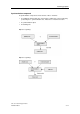
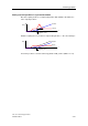
3.4.1 Structure of the "Synchronization axis" technology object
Synchronization objects and following axes are separate objects, but form a
common synchronous axis.
The "Synchronous Operation" and "Axis" technology objects have a reciprocal
effect on each other depending on their respective operating modes and which
commands are in effect.
If an error has occurred only at the synchronization object, the following axis can
still continue positioning, but not synchronous operation. In order to avoid this
effect, always acknowledge the errors. Errors at the "Axis" technology object
therefore have a direct reciprocal effect on the synchronization object functions.
Axis stop also triggers the stop of synchronous motion.
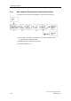
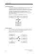
3.4.2 Synchronization compound
The "Synchronization axis" technology object can be used to interconnect axes to
form a synchronization compound.
Example
A leading axis generates a control value. The synchronization object processes this
value, based on defined criteria (gear ratio, scaling, offset, cam disk) and assigns it
to the following axis as command variable.
Note
The control values and following values are coupled without physical conversion in
the relevant assigned units. If, for example, the leading axis is a linear axis (in mm
units), and the following axis is a rotary axis (in degree units), then one millimeter
is proportional to one degree, at a conversion ratio of 1:1.
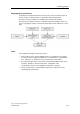
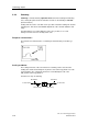
Example of mechanical synchronism
Gear synchronism is given, for example, when two mechanically coupled rollers
are driven by the same motor.
The camming model could be a cam gear with a mechanical cam and sensing
mechanism.
The synchronization and sync off FBs of a synchronization compound correspond
with the function of a mechanical coupling.