
Technical data


Technology functions
CPU 317T: Technology Functions
6-162 A5E00251798-03
MC_GearInSuperImposed - Example of "Phase shift"
The signal profile in the example below shows the differences between absolute
superimposing synchronism with and without phase shift. In order to keep the
example as simple as possible, we have excluded base synchronism from the
signal profile shown.
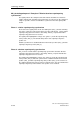
Absolute superimposing synchronism without phase shift
Start positions at the start of the signal profile:
• Master position (Axis_1) = 0
• Slave position (Axis_2) =
• superimposing slave position = 0
A positive edge at Exe_1 starts absolute superimposing synchronism without
phase shift. After a short delay, InGear_1 reports that absolute superimposing
synchronism is reached.
The signal flow highlighted in orange color indicates the superimposing slave
position. The default start position of the superimposing slave position is 0.
Absolute synchronism is established between the master position (Axis_1) and the
superimposing slave position (Axis_2).
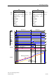
Absolute superimposing synchronism with phase shift
The signal profile applies to the start positions in analog to the signal profile without
phase shift.
• Master position (Axis_1) = 0
• Slave position (Axis_2) =
• superimposing slave position = 0
A positive edge at Exe_2 starts absolute superimposing synchronism with phase
shift. After a short delay, InGear_2 reports that absolute superimposing
synchronism is reached.
This time, however, the orange-colored signal profile shows the superimposing
slave position (Axis_2) with the specified phase shift. The default start position of
the superimposing slave position is again 0.