
Technical data


Configuration
CPU 317T: Technology Functions
4-108 A5E00251798-03
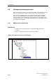
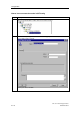
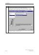
4.9.2 Configuration - Measuring Sensor
in the Measuring input > Configuration dialog box you can set the following
functions for the "measuring input" technology object:
• Meas.input cycle clock: IPO, IPO2 or position control cycle clock. By default,
the measurement results are written to the system variables of the technology
object based on the interpolator cycle.
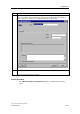
• The measuring sensor number: corresponds with the number of the measuring
input used at the drive component (only if "Measuring sensor at TM15/TM17" is
disabled.) One specific measuring input can be assigned to several measuring
inputs.
• The system number: corresponds with the number of the encoder system used
(if several encoders are configured at the axis, otherwise 1). One specific
encoder system can be assigned to several measuring sensors.
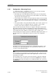
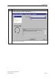
Set the "monitor current status" check box to suppress short pulses (shorter than
the position controller cycle) at the measuring sensor input. A measuring sensor
triggered at the positive edge is not enabled until the signal status at the measuring
sensor input was 0 for the duration of at least one position controller cycle.
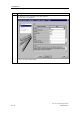
If the measuring sensor input is located on a TM15/TM17 High Feature module, set
the "Measuring sensor at TM15/TM17 module" check box in the configuration
dialog.
An input box opens after you set the check box, showing the byte address of the
measuring sensor signal at DP(DRIVE), and a drop-down list in which you can
select the corresponding bit number.
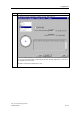
Note
The measuring sensor input must be located either on the drive component used,
or on a TM15/TM17 High Feature module. Other digital inputs can not be used as
measuring sensor inputs.
The measuring sensor can only be connected to the drive component containing
the encoder input. If the encoder input is connected to SIMODRIVE, for example,
you can only connect the measuring sensor to ADI4 if the ADI4 is also connected
to SIMODRIVE.