
Technical data

Configuration
CPU 317T: Technology Functions
4-72 A5E00251798-03
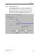
4.6.1 Assigning leading axes and cam disks
In you configuration of a synchronization compound you need to assign a leading
axis to the synchronization axis. In order to be able to run a synchronization
compound in camming mode, the synchronization axis should also be logically
linked with a cam disk.
Requirements
• A synchronization axis was added in S7T Config.
• A leading axis and a cam disk were added in S7T Config.
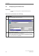
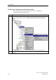
How to assign leading axes and cam disks to a synchronization axis
The principle is shown in the next steps.
Step Description
1.
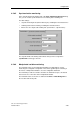
In the S7T Config Navigator, double-click _ SYNCHRONOUS_OPERATION in the <axis name>
synchronization object.
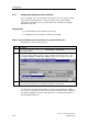
2. In the next dialog box, assign a leading axis to the synchronization axis. To do so, set the check
box in the left column, and then select the relevant coupling mode. For physical axes, select
either Setpoint coupling or Actual value coupling. External encoders support only actual
value coupling, and virtual axes only support setpoint coupling.
3. Click "Close"
Result: The synchronization axis is assigned the leading axes and cam disks.
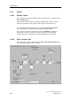
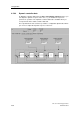
You may interconnect the synchronization axis with several leading axes. Which
one of axes is to provide the control value to the synchronization axis is determined
in runtime by calling the relevant technology function, for example, MC_GearIn or
"MC_CamInSuperImposed".