
Technical data
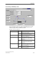

Configuration
CPU 317T: Technology Functions
4-48 A5E00251798-03
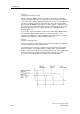
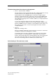
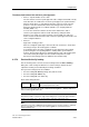
• Phase 2:
Synchronization with zero mark
After it reaches the BERO, the axis accelerates / decelerates to shutdown
velocity, and approaches the zero mark derived from the combined settings of
"zero mark" (after or before BERO) and "Direction of reference point approach"
(positive or negative.) The PLC synchronizes the axis to the first zero mark
detected after the BERO is detected in accordance with the configuration. The
axis position is set to the default value minus the homing position offset value
defined in "Homing position coordinate" (Mode = 0) or at input parameter
Position (Mode = 1.)
You can also monitor the distance an axis travels between the BERO and the
zero mark by setting the "Max. distance to zero mark" check box. The
reference point approach is canceled with error if the zero mark is not found
within the specified distance after the BERO is detected.
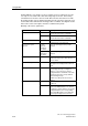
• Phase 3:
Reference point approach
After the zero mark is detected, the axis accelerates / decelerates to approach
velocity and approaches the homing position.
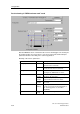
If a homing position offset was configured, the axis approaches the homing
position along the corresponding distance, starting at the synchronization
position. The traversing direction is determined by the sign of the homing point
offset value and by the length of the deceleration ramp after zero mark
detection, if the homing position lies within the deceleration ramp.