
Technical data


Configuration
CPU 317T: Technology Functions
4-40 A5E00251798-03
4.5.6.2 Hardware limit switches
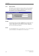
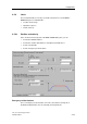
Hardware limit switch monitoring is enabled in the Axis > Limits dialog box, in the
"Position and velocity" tab. Hardware limit switch monitoring is used to limit the
operating range of an axis, or to protect the machine.
Connection
HW limit switches can be connected via four integrated digital inputs of the
Technology CPU, or the I/O operated on DP(DRIVE) (ET 200, SINAMICS S120
with TM15/TM17, for example.)
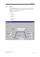
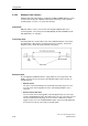
Traversing range
Traversing limits are monitored by means of the HW limit switches connected to
the digital inputs. HW switches are always break action switches, and should
always be active outside the permissible traversing range.
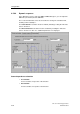
Release motion
An axis triggering a HW limit switch is stopped with error messages 8013 and
804B. It is released out of the range of the HW limit switch (release motion) as
described below:
• Manual release
The axis is returned manually to the permissible traversing range. The error
message at the technology DB can not be acknowledged until the axis is
released.
• Release motion with drive
The error at the axis technology DB is acknowledged, but the error message
and the LimitSwitchActive status bit remain active. The axis can now be moved
into its permitted traversing range. A reverse motion command once again
triggers an axis error. The LimitSwitchActive status can be acknowledged after
the axis has moved out of the range of the limit switch.