
Technical data


Preparation
2
2.1 2.1 Requirements
Requirements
The following requirements must be fulfilled:
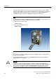
• An S7-300 station, consisting of:
– Power supply module (PS), for example, 6ES7 307-1EA00-0AA0
– CPU 317T-2 DP with inserted MMC (4 MB or more).
– Optional digital input module (DI) with bus connector, for example,
6ES7 321-1BH02-0AA0
– Optional digital output module (DO) with bus connector, for example,
6ES7 322-1BH01-0AA0
– Two optional front connectors for the digital modules
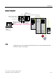
• A PG with MPI interface and properly installed software packages and commissioning
tools as listed below:
– STEP 7 V5.3 SP3 and higher
– S7-Technology V3.0
• The PG is connected to the CPU via the MPI/DP interface (transmission rate up to 12
Mbps; default 187.5 kbps).
• A SINAMICS
®
S120 is connected to the CPU 317T-2 DP via the DP (DRIVE) interface.
• The SINAMICS
®
S120 comprises the following modules:
– CU320 control unit with TB30 terminal board (6SL3040-0MA00-0AA1)
– Smart line module, 5 kW (6SL3130-6AE15-0AA0-Z)
– Single/double motor module, 3 A (6SL3120-2TE13-0AA0-Z)
– 1 synchronous motor 1FK7022-5AK71-1AG3 with incremental encoder sin/cos 1 Vpp
via SMC20 sensor module cabinet (6SL3055-0AA00-5BA1)
– 1 synchronous motor 1FK7022-5AK71-1LG3 with DRIVE-CLiQ interface: Absolute
encoder EnDat 512 pulses/revolution
– Reference loops for position monitoring
– Control box for setpoint/actual-value linkage via terminals
• You know the firmware version of your SINAMICS S120.
CPU 317T-2 DP: Controlling a SINAMICS S120
Getting Started, 12/2005, A5E00480391-01
2-1