SIMATIC S7 300 PLC CPU 317T-2 DP: Controlling a SINAMICS S120 1 Introduction ______________ 2 Preparation ______________ SIMATIC S7 300 PLC CPU 317T-2 DP: Controlling a SINAMICS S120 Getting Started 12/2005 A5E00480391-01 3 Learning units ______________ 4 Further information ______________
Safety Guidelines This manual contains notices you have to observe in order to ensure your personal safety, as well as to prevent damage to property. The notices referring to your personal safety are highlighted in the manual by a safety alert symbol, notices referring only to property damage have no safety alert symbol. These notices shown below are graded according to the degree of danger. Danger indicates that death or severe personal injury will result if proper precautions are not taken.
Table of contents 1 Introduction............................................................................................................................................. 1-1 1.1 2 Preparation ............................................................................................................................................. 2-1 2.1 3 4 Introduction ................................................................................................................................
Table of contents iv CPU 317T-2 DP: Controlling a SINAMICS S120 Getting Started, 12/2005, A5E00480391-01
Introduction 1.1 1.1 1 Introduction Introduction This Getting Started contains a practical example guiding you through thirteen steps in commissioning a fully functional application, and showing you how to carry out motion commands. It is thus a valuable help in getting started with the basic functions of a CPU 317T-2 DP. Depending on your degree of experience, working through the sample will take between two and three hours.
Introduction 1.
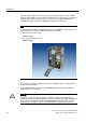
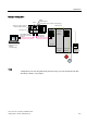
2 Preparation 2.1 2.1 Requirements Requirements The following requirements must be fulfilled: • An S7-300 station, consisting of: – Power supply module (PS), for example, 6ES7 307-1EA00-0AA0 – CPU 317T-2 DP with inserted MMC (4 MB or more).
Preparation 2.1 Requirements If you do not know the firmware version, then you can find the version on the supplied certificate. Alternatively, you can open the "content.txt" file on the CF card. The firmware version is in the "Internal Version" entry. You can find more detailed information on reading the firmware version in the SINAMICS S120 product information. Note For the example of a drive in Getting Started, we use a SINAMICS® S120 training case.
Preparation 2.
Preparation 2.
3 Learning units 3.1 3.1 1. Step: Wiring Warning You may come into contact with live wires. Always switch off power before you start wiring the S7-300. Procedure A description of the installation and wiring of your 317T-2DP CPU is found in the Getting Started Collection S7-300 PLC: CPU 31x: Commissioning. Set the PROFIBUS address of the SINAMICS® to PROFIBUS address 4.
Learning units 3.2 2. Step: Configuring CPU 317T-2 DP with HW Config 352),%86 LQWHUIDFH $GGUHVV 3.2 3.2 2. Step: Configuring CPU 317T-2 DP with HW Config Procedure Sequence Activity Result 1 Create a new project in the SIMATIC Manager (for example, "GS_317T2-DP_with_S120") and add a SIMATIC 300 station. The SIMATIC 300 station appears in the SIMATIC Manager. 2 Open HW Config by selecting the "SIMATIC 300" station and doubleclicking "Hardware". HW Config opens.
Learning units 3.2 2. Step: Configuring CPU 317T-2 DP with HW Config Sequence Activity 3 Open the "Hardware Catalog" and select the "SIMATIC Technology CPU" hardware profile in the "Profile" drop-down list. Result Result: The "SIMATIC Technology" directory is displayed. 4 Insert a mounting rail using drag-and-drop in the station window of HW Config. This creates a mounting rail. 5 Drag-and-drop the "PS 307 5A" power supply module onto the mounting rail.
Learning units 3.3 3. Step: Changing the transmission rate at the MPI/DP interface Sequence Activity 9 Add a digital input module and a digital output module. Result You now have this layout: 3.3 3.3 3. Step: Changing the transmission rate at the MPI/DP interface Procedure Sequence Activity Result 1 Open the MPI/DP interface (X1) in HW Config with doubleclick. The "Properties - MPI/DP" dialog box opens. 2 Click "Properties". The "Properties – MPI interface MPI/DP" dialog box opens.
Learning units 3.4 4. Step: Vital settings in your DP (DRIVE) configuration Sequence Activity 4 Select the "Network settings" tab and select a transmission speed of "1.5 Mbps". 5 Confirm all open dialog boxes with "OK". You have now increased the configured transmission speed of the MPI interface at the CPU in order to accelerate data transfer. 6 When the CPU is in STOP, select PLC > Download to download the configuration. Select the CPU and confirm with "OK".
Learning units 3.5 5. Step: Generating technology system data 3.5 3.5 5. Step: Generating technology system data Procedure Sequence Activity Result 1 Double-click "Technology" on the mounting rail. The "Properties - Technology" dialog box opens. 2 Select the "Technology system data" tab, then set the "Generate technology system data" check box. Confirm with "OK".
Learning units 3.6 6. Step: Configuring the drive in HW Config 3.6 3.6 6. Step: Configuring the drive in HW Config Procedure Sequence Activity 1 In the HW catalog, open the tree structure SIMATIC Technology > PROFIBUS DP (DRIVE) > Drives > SINAMICS. 2 Select the drive component "SINAMICS S120" from the tree structure of the HW catalog. 3 Drag-and-drop this component to the master system of the DP (DRIVE). The "Properties – PROFIBUS interface SINAMICS" dialog box opens.
Learning units 3.6 6. Step: Configuring the drive in HW Config Sequence Activity 5 Select the appropriate drive version for your SINAMICS® and confirm with "OK". 6 The "DP Slave Properties" dialog box opens. Select the "Clock Synchronization" tab. 3-8 Result The "Clock Synchronization" dialog box opens.
Learning units 3.6 6. Step: Configuring the drive in HW Config Sequence Activity 7 Set the "Synchronize drive with equidistant DP cycle", then set the time coefficients as shown below. Result 8 Click "Alignment". 9 Confirm with "OK". The following components are aligned to the set values: • DP cycle in the DP master system • All drive components of the same family (here SINAMICS®) are aligned to the set values. 10 Confirm the possible warning with "OK".
Learning units 3.7 7. Step: Configuration of the PG/PC interface 3.7 3.7 7. Step: Configuration of the PG/PC interface Procedure Sequence Activity Result 1 Start the NetPro network configuration program in HW Config with Options > Configure network. NetPro is started 2 In the HW catalog, open the tree structure Stations > PG/PC and drag-and-drop a PG/PC station into the "Network View" window.
Learning units 3.7 7. Step: Configuration of the PG/PC interface Sequence Activity 3 Select the newly inserted PG/PC component and open the "Properties – PG/PC" dialog box with Edit > Object properties….
Learning units 3.7 7. Step: Configuration of the PG/PC interface Sequence Activity 4 Select the "Interfaces" tab in the "Properties – PG/PC" dialog box. Result Click the "New…" button to open the "New Interface – Type Selection" dialog box. Select "MPI" and confirm with "OK". Result: The "Properties - MPI Interface" dialog box opens.
Learning units 3.7 7. Step: Configuration of the PG/PC interface Sequence Activity 5 In the "Properties - MPI Interface" dialog box, select address "1" and the "MPI network". Confirm your input with "OK".
Learning units 3.7 7. Step: Configuration of the PG/PC interface Sequence Activity 6 Select the "Assignment" tab in the "Properties – PG/PC" dialog box. Result Assign the MPI interface parameterization in the PG/PC to the configured interface by clicking "Assign".
Learning units 3.7 7. Step: Configuration of the PG/PC interface Sequence Activity 7 Complete the configuration by clicking "OK".
Learning units 3.7 7. Step: Configuration of the PG/PC interface Sequence Activity 8 You have now inserted your PG/PC in the MPI network and established the condition to exchange data with the SINAMICS® control. Result 9 Complete the network configuration by calling the Network > Save and compile command. Select "Compile and check everything" and confirm with "OK".
Learning units 3.7 7. Step: Configuration of the PG/PC interface Sequence Activity 10 Close the output window with File > Close. 11 Close the NetPro configuration program by calling the Network > Exit command.
Learning units 3.8 8. Step: Downloading the hardware configuration to the target hardware 3.8 3.8 8. Step: Downloading the hardware configuration to the target hardware Procedure Sequence 1 Activity Result Switch back to HW Config Download the hardware configuration to the CPU by calling the PLC > Download … command.
Learning units 3.8 8. Step: Downloading the hardware configuration to the target hardware Sequence Activity 2 Select the "CPU317T-2DP" and confirm with "OK".
Learning units 3.8 8. Step: Downloading the hardware configuration to the target hardware Sequence Activity 3 Enter the MPI address of your destination address and confirm with "OK". Result Result: The data are now downloaded from the PG to the CPU. 4 3-20 Also close the HW Config by calling the Station > Exit command.
Learning units 3.9 9. Step: Configuration of the SINAMICS drive with S7T Config 3.9 3.9 9. Step: Configuration of the SINAMICS drive with S7T Config Procedure Sequence Activity Result 1 In SIMATIC Manager, double-click "Technological Objects“ to open S7T Config. Result: "Technological Objects Management" opens. The system automatically runs S7T Config if you have not configured any technological objects yet, as in this example.
Learning units 3.9 9. Step: Configuration of the SINAMICS drive with S7T Config Sequence Activity 3 Change to the online mode by selecting the Project > Connect to target system command. 4 In the project navigator, open the tree structure SIMATIC 300(1) > Technology > SINAMICS_S120 > Automatic configuration. Open the automatic configuration by double-clicking "Automatic configuration".
Learning units 3.9 9. Step: Configuration of the SINAMICS drive with S7T Config Sequence Activity 5 Start the automatic configuration in the "Automatic Configuration" dialog box by clicking the "Start automatic configuration" button. 6 Set the drive object type for both motors to "Servo" and exit the dialog box with "Finish".
Learning units 3.9 9. Step: Configuration of the SINAMICS drive with S7T Config Sequence Activity 7 The SINAMICS® training case on which this document is based has two different motor types. One of the two motor types has DRIVE-CLIQ technology. The second motor/encoder is connected via SMC20, which is why DRIVE-CLiQ recognizes that a second motor/encoder is present and creates this, but cannot automatically configure it. Therefore, not all drive information can be completely configured automatically.
Learning units 3.9 9. Step: Configuration of the SINAMICS drive with S7T Config Sequence Activity 9 Change to the offline mode by selecting the Project > Disconnect from target system command.
Learning units 3.9 9. Step: Configuration of the SINAMICS drive with S7T Config Sequence Activity 10 In the project navigator, open the tree structure SIMATIC 300(1) > Technology > SINAMICS_S120 > Drives > Servo_03 > Configuration. Open the offline drive configuration by double-clicking "Configuration".
Learning units 3.9 9. Step: Configuration of the SINAMICS drive with S7T Config Sequence Activity 11 Click the "Configure DDS..." button to start the configuration.
Learning units 3.9 9. Step: Configuration of the SINAMICS drive with S7T Config Sequence Activity 12 Accept the default settings and click "Continue >".
Learning units 3.9 9. Step: Configuration of the SINAMICS drive with S7T Config Sequence Activity 13 The power section has DRIVE-CLIQ technology and has already been correctly configured. Check the order number and click "Continue >".
Learning units 3.9 9. Step: Configuration of the SINAMICS drive with S7T Config Sequence Activity 14 The SINAMICS® training case on which this document is based does not have an active infeed module. Confirm the warning with "OK". 15 Click the blue button and in the TB30_04 context menu, select digital input 0, which corresponds to parameter r4022, bit 0. Then click "Continue >".
Learning units 3.9 9. Step: Configuration of the SINAMICS drive with S7T Config Sequence Activity 16 The motor without complete DRIVE-CLIQ technology is connected to terminal X2 of the power section. Click "Continue >".
Learning units 3.9 9. Step: Configuration of the SINAMICS drive with S7T Config Sequence Activity 17 Select the correct motor from the list. To activate the selection option, you must select the "Select standard motor from list" box. Result The motor used in the SINAMICS® training case is the 1FK7022-xAK7x-xxxx. Check this against the supplied documents or the motor type plate (lower motor - blue gear wheel). Select the appropriate motor and click "Continue >".
Learning units 3.9 9. Step: Configuration of the SINAMICS drive with S7T Config Sequence Activity 18 Select "Without holding brake" and click "Continue >".
Learning units 3.9 9. Step: Configuration of the SINAMICS drive with S7T Config Sequence Activity 19 Select 1FK7xxx-xxxxx-xAxx. Check this against the supplied documents and click "Continue >".
Learning units 3.9 9. Step: Configuration of the SINAMICS drive with S7T Config Sequence Activity 20 Set the PROFIBUS message frame to "SIEMENS telegram 105 (105)" and click "Continue >".
Learning units 3.9 9. Step: Configuration of the SINAMICS drive with S7T Config Sequence Activity 21 Click the "Finish" button to exit the offline configuration of the drive.
Learning units 3.9 9. Step: Configuration of the SINAMICS drive with S7T Config Sequence Activity 22 The offline configuration of the drive is completed. Close the dialog box with the "Close" button.
Learning units 3.9 9. Step: Configuration of the SINAMICS drive with S7T Config Sequence Activity 23 In the project navigator, open the tree structure SIMATIC 300(1) > Technology > SINAMICS_S120 > Drives > Servo_03. Result Right-click to open the context menu and select Expert > Expert list.
Learning units 3.9 9. Step: Configuration of the SINAMICS drive with S7T Config Sequence Activity 24 Select parameter "p210" and enter "345". Result The smart line module and the motor module of the SINAMICS S120 training case have been especially equipped for operation on a 230 V system.
Learning units 3.9 9. Step: Configuration of the SINAMICS drive with S7T Config Sequence Activity 25 In the project navigator, open the tree structure SIMATIC 300(1) > Technology > SINAMICS_S120 > Drives > Servo_02 > Configuration. Double-click "Configuration" to open the offline drive configuration.
Learning units 3.9 9. Step: Configuration of the SINAMICS drive with S7T Config Sequence Activity 26 Start the configuration by clicking the "Configure DDS…" button.
Learning units 3.9 9. Step: Configuration of the SINAMICS drive with S7T Config Sequence Activity 27 Accept the default settings and click "Continue >".
Learning units 3.9 9. Step: Configuration of the SINAMICS drive with S7T Config Sequence Activity 28 The power section has DRIVE-CLIQ technology and has already been correctly configured. Check the order number and click "Continue >".
Learning units 3.9 9. Step: Configuration of the SINAMICS drive with S7T Config Sequence Activity 29 The SINAMICS® training case on which this document is based does not have an active infeed module. Confirm the warning with "OK". 30 Click the blue button and in the TB30_04 context menu, select digital input 0, which corresponds to parameter r4022, bit 0. Then click "Continue >".
Learning units 3.9 9. Step: Configuration of the SINAMICS drive with S7T Config Sequence Activity 31 The motor with complete DRIVE-CLIQ technology is connected to terminal X1 of the power section. Click "Continue >".
Learning units 3.9 9. Step: Configuration of the SINAMICS drive with S7T Config Sequence Activity 32 The motor with complete DRIVE-CLIQ technology has already been correctly configured. Click "Continue >".
Learning units 3.9 9. Step: Configuration of the SINAMICS drive with S7T Config Sequence Activity 33 Click "Continue >".
Learning units 3.9 9. Step: Configuration of the SINAMICS drive with S7T Config Sequence Activity 34 The correct encoder has already been correctly configured by means of DRIVE-CLIQ technology. Click "Continue >".
Learning units 3.9 9. Step: Configuration of the SINAMICS drive with S7T Config Sequence Activity 35 Set the PROFIBUS message frame to "SIEMENS telegram 105 (105)" and click "Continue >".
Learning units 3.9 9. Step: Configuration of the SINAMICS drive with S7T Config Sequence Activity 36 Click the "Finish" button to exit the offline configuration of the drive.
Learning units 3.9 9. Step: Configuration of the SINAMICS drive with S7T Config Sequence Activity 37 The offline configuration of the drive is completed. Close the dialog box with the "Close" button.
Learning units 3.9 9. Step: Configuration of the SINAMICS drive with S7T Config Sequence Activity 38 In the project navigator, open the tree structure SIMATIC 300(1) > Technology > SINAMICS_S120 > Drives > Servo_02. Result Right-click to open the context menu and select Expert > Expert list.
Learning units 3.9 9. Step: Configuration of the SINAMICS drive with S7T Config Sequence Activity 39 Select parameter "p210" and enter "345". Result The smart line module and the motor module of the SINAMICS S120 training case have been especially equipped for operation on a 230 V system.
Learning units 3.9 9. Step: Configuration of the SINAMICS drive with S7T Config Sequence Activity 41 In the "SINAMICS_S120 – Configuration" dialog box, set both message frame types to "SIEMENS telegram 105" and then click the "Align with HW Config" button. 42 Close the "SINAMICS_S120 – Configuration" dialog box by clicking "Close".
Learning units 3.9 9. Step: Configuration of the SINAMICS drive with S7T Config Sequence Activity 43 Select the Project > Save and recompile all menu command to save and compile the entire technology project. 44 Select the Project > Connect to target system menu command to switch to online mode.
Learning units 3.9 9. Step: Configuration of the SINAMICS drive with S7T Config Sequence Activity 45 The desired configuration is on the PG/PC. Click the "<== Download" button to transfer the configuration to the drive. 46 Confirm the safety query with "Yes".
Learning units 3.9 9. Step: Configuration of the SINAMICS drive with S7T Config Sequence Activity 47 Close the dialog message with "OK". 48 Close the dialog box with "Close".
Learning units 3.9 9. Step: Configuration of the SINAMICS drive with S7T Config Sequence Activity 49 Select the Project > Disconnect from target system menu command to switch to offline mode. 50 Activate the check boxes "Copy RAM to ROM" and "Load changes to PG/PC". Then confirm with "OK".
Learning units 3.10 10. Step: Configuring the axes with S7T Config 3.10 3.10 10. Step: Configuring the axes with S7T Config Important information In this step, you create your technology objects (e.g. axes) with S7T Config. Use "Technology Objects Management“ to generate a technology DB for each TO. Do not copy the technology DBs in order to ensure a defined assignment between the technology DB and its TO.
Learning units 3.10 10. Step: Configuring the axes with S7T Config Sequence Activity 2 Confirm the default technology selection (speed control, positioning) with "OK". Result Result: The "Axis Configuration - Axis_1 – Axis Type" dialog box opens.
Learning units 3.10 10. Step: Configuring the axes with S7T Config Sequence Activity 3 Accept the "Axis type: Linear, electric" and "Motor type: standard motor". Confirm with "Continue". Result Result: The "Axis configuration - Axis_1 - Units" dialog box opens.
Learning units 3.10 10. Step: Configuring the axes with S7T Config Sequence Activity 4 Confirm with "Continue". Result Result: The "Axis configuration Axis_1 - Modulo" dialog box opens.
Learning units 3.10 10. Step: Configuring the axes with S7T Config Sequence Activity 5 Confirm with "Continue". Result Result: The "Axis Configuration - Axis_1 Drive Assignment" dialog box opens.
Learning units 3.10 10. Step: Configuring the axes with S7T Config Sequence Activity 6 Click the "Align Sinamics devices..." button. 7 Select the "SINAMICS_S120" device and click "Align". Result Result: The "Axis Configuration - Axis_1 Drive Assignment" dialog box opens again. 8 3-64 Select your "actual drive unit (SINAMICS_S120)".
Learning units 3.10 10. Step: Configuring the axes with S7T Config Sequence Activity 9 The configured message frame is taken over from the drive configuration and must be confirmed in this dialog box. Enter the maximum motor speed as "Rated speed“ (see motor type plate). Set a maximum motor speed of 6000 rpm for our example. Confirm your settings with "Continue". Result Result: A message box appears. 9 Close the message box with "OK". The "S7T Config Help" online help opens.
Learning units 3.10 10. Step: Configuring the axes with S7T Config Sequence Activity 11 Select the encoder type and mode, and the measuring system. Settings for the first axis in our example: • "Encoder type" is an "Absolute encoder" • "Encoder mode" is "Endat" • "Measuring system" is "Rotary encoder system" Result Confirm with "Continue". Result: The "Axis Configuration - Axis_1 - Encoder - Data" dialog box opens.
Learning units 3.10 10. Step: Configuring the axes with S7T Config Sequence Activity 12 Enter the resolution specified on your motor rating plate as well as the number of data bits. In our example, the number of encoder pulses is "512" and the number of data bits is "21". Result Accept the settings with "Continue". If you use another encoder type, you can find appropriate examples for the encoder configuration in the online help of S7T Config.
Learning units 3.10 10. Step: Configuring the axes with S7T Config Sequence Activity Result 16 Select Project > Save and recompile all to save the configuration in S7T Config. The system now compiles the axis configuration data. Note: Repeat sequence 1 to 16 in step number 10 if you are using a double axis module. The SINAMICS® demonstration case has a motor module with absolute encoder and a motor module with incremental encoder.
Learning units 3.10 10.
Learning units 3.11 11. Step: Creating the technology DBs 3.11 3.11 11. Step: Creating the technology DBs Procedure Sequence Activity Result 1 Change to "Technological Objects Management". Confirm the first message box with "OK", and the second with "Yes". If you are not running the "Technological Objects Management“ application yet, you can open it by doubleclicking "Technological Objects“ in the "Technology“ folder in SIMATIC Manager (see also step: "Configuring the axes with S7T Config").
Learning units 3.12 12. Step: Controlling the axis with the STEP 7 user program 3.12 3.12 12. Step: Controlling the axis with the STEP 7 user program Procedure Sequence Activity Result 1 In SIMATIC Manager, open the sample project "\Examples\PROJECT-CPU317T".
Learning units 3.13 13. Step: Trial run 3.13 3.13 13. Step: Trial run Procedure Sequence Activity Result 1 In the "Blocks" folder of your project, double-click the "AxisData" variable table. The variable table is opened for monitoring. 2 Select PLC > Connect to > Configured CPU to go online. The CPU "STOP" status is indicated on the bottom right. 3 Select Variable > Monitor to set monitoring mode. The "Status value" column shows the actual values of the addresses.
Further information 4.1 4.1 4 Further information Diagnostics / correction of errors Incorrect operator input, faulty wiring or inconsistent configuration data may lead to errors. For information on how to analyze such errors and messages, refer to the S7-Technology manual. Service and support on the Internet In addition to our documentation, we offer a comprehensive online knowledge base on the Internet at: http://www.siemens.
4 4.1 4.