
Computer Accessories User Manual


CANpro/104 User Manual
CTIM-00043 (0.01) 1/15/2010 www.connecttech.com 8
800-426-8979 | 519-836-1291
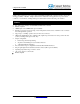
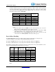
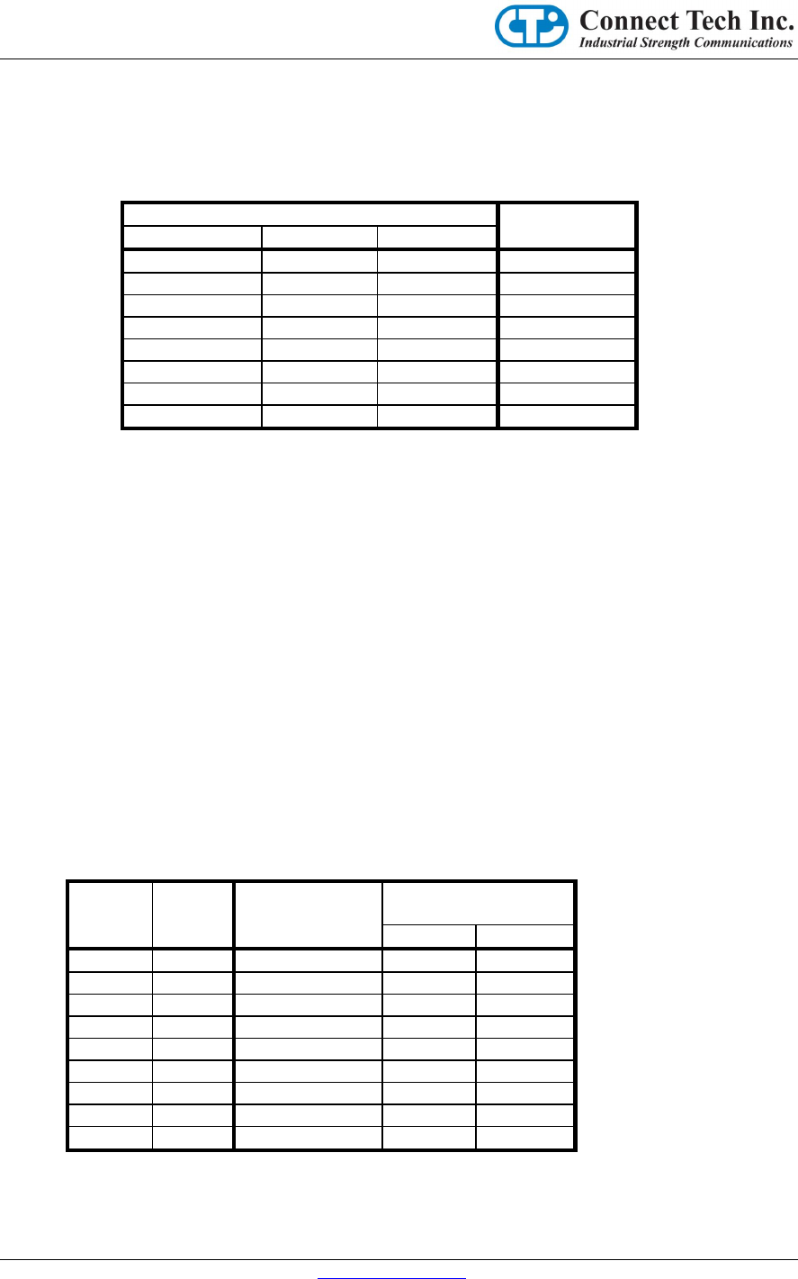
Secondly, the Memory Space can be enabled by Application or Driver software, after the Operating
system has started. This can be accomplished by writing a data value to an I/O Space Address which
is decoded by the following J3B Jumper settings. Only one byte of the I/O Space is decoded at this
I/O Address, and the location is Write Only.
J3B
I/O Address
Position #5
Position #6
Position #7
Removed
Removed
Removed
0x200
Removed
Removed
Installed
0x240
Removed
Installed
Removed
0x280
Removed
Installed
Installed
0x2C0
Installed
Removed
Removed
0x300
Installed
Removed
Installed
0x340
Installed
Installed
Removed
0x380
Installed
Installed
Installed
0x3C0
Table 3
Notes:
1. These I/O address choices do NOT access the CAN Controllers, they are used in
Memory Mode to enable the Memory Space address decoding.
2. Writing a data value of 0xA5 will enable the Memory Space, and a data value of 0x5A
will disable the Memory Space. All other data values written will be ignored.
3. When the Memory Space is permanently enabled (when J3C-1 is removed), any data
value written to the “Memory Enable” I/O address will be ignored.
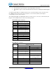
Base Address Decoding
The CTI CANpro/104 board decodes its Base Address setting (in either Memory or I/O Spaces) by
comparing (matching) various Jumper settings with PC/104 Bus Address bits.
If a Jumper is installed, then the corresponding Address Bit will be matched as a logical “1”.
If a Jumper is removed, then the corresponding Address Bit will be matched as a logical “0”.
The matching of Jumper settings to Address bits depends on whether the board is operated in Memory or I/O
Spaces, and whether PeliCAN or BasicCAN mode is selected.
Jumper
Group
Position
Memory Space
Address Bit
I/O Space
Address Bit
PeliCAN
BasicCAN
J3A
2
23
X
X
3
22
X
X
4
19
X
X
5
18
X
X
6
17
10
10
J3B
1
16
9
9
2
15
8
8
3
14
X
7
4
13
X
6
Table 4
Notes: