USER MANUAL CANpro/104 CTIM-00043 (0.
CANpro/104 User Manual Table of Contents Copyright Notice ................................................................................................................................................ 4 Trademark Acknowledgement ............................................................................................................................ 4 Revision History ........................................................................................................................................
CANpro/104 User Manual J3A .......................................................................................................................................................... 16 J3B .......................................................................................................................................................... 17 J3C ..........................................................................................................................................................
CANpro/104 User Manual Copyright Notice The information contained in this document is subject to change without notice. Connect Tech Inc. shall not be liable for errors contained herein or for incidental consequential damages in connection with the furnishing, performance, or use of this material. This document contains proprietary information that is protected by copyright. All rights are reserved.
CANpro/104 User Manual Introduction CANpro/104 combines the power of two independent NXP SJA1000 CAN controllers with the compact size and rugged stability of PC/104. CANpro/104 is ideal for industrial control applications exposed to harsh conditions or environments. CANpro/104 Opto models feature 2.5 kV of data and power isolation.
CANpro/104 User Manual Hardware Installation – Rev C & Later The Connect Tech CANpro/104 board provides two (2) industry standard SJA1000 CAN Bus controllers in a PC/104 board format which supports both I/O and Memory mapping configurability. All the configuration options are setup with jumpers, identified as J1, J2, J3A, J3B, J3C, J4 and J5. Jumpers are always oriented as indicated in the drawing below. The jumper positions are numbered on the PCB (and are shown in the above drawing).
CANpro/104 User Manual I/O Space This region is supported by all PC/104 CPU System board vendors, and commonly consists of I/O Addresses from 0x000 to 0x3FF, although some System boards support I/O addresses beyond 0x3FF. (Note: Some I/O mapped PC/104 expansion boards only decode the lowest 10 bits of the I/O address, therefore these boards restrict the usable I/O space to 0x3FF).
CANpro/104 User Manual Secondly, the Memory Space can be enabled by Application or Driver software, after the Operating system has started. This can be accomplished by writing a data value to an I/O Space Address which is decoded by the following J3B Jumper settings. Only one byte of the I/O Space is decoded at this I/O Address, and the location is Write Only.
CANpro/104 User Manual 1. 2. X = Address bit is ignored (and the corresponding Jumper is Not Used). When Memory Space is selected, PC/104 Address bits 20 and 21 are always decoded as logical “0”. To determine which Jumpers to install and which to remove, the desired Address needs to be broken down into a binary number, all the Jumpers that correspond to “1-bits” must be installed, and all Jumpers corresponding to “0-bits” must be removed.
CANpro/104 User Manual PeliCAN vs BasicCAN Addressing Modes The SJA1000 can operate in 2 different modes, the PeliCAN mode which has extended features and additional registers and which consume 128 bytes of address space per device (there are 2 devices on this board). And, the BasicCAN mode which has reduced functionality but only consumes 32 bytes of register space per device.
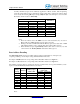
CANpro/104 User Manual Example #2: Memory Address 0x0C8000 (this address is below the 1-Meg boundary) 0x0C8000 = 0000.1100.100X.XXXX.CJJJ.JJJJ (binary) Address Bit 23 22 21 20 19 18 17 16 15 14 13 Table 9 Example #3: Bit Value X 0 1 1 0 1 J3A or J3B Position --J3A-6 J3B-1 J3B-2 J3B-3 J3B-4 Installed or Removed --Removed Installed Installed Removed Installed I/O Address 0x600 (PeliCAN mode) 0x600 = XXXX.XXXX.XXXX.X110.CJJJ.
CANpro/104 User Manual CAN Controller Addressing Table Once the Base Memory or I/O Address is setup, the 2 SJA1000 CAN controllers are accessed at the following address offsets.
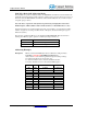
CANpro/104 User Manual Common Memory Space Address Selections Most System boards allow the PC/104 Bus stack to be allocated a portion of the memory address located in the 256K region of memory just below the 1-Meg address boundary (Addresses 0x0C0000 to 0x0FFFFF). Different BIOS’s allow different sized regions to the allocated. The CANpro/104 board requires 8K (8192 bytes) of memory space. The following table shows the Jumpers required to set up the Base Memory Address within this 256K region.
CANpro/104 User Manual Performance Enhancement PC/104 Memory and I/O Bus cycles are typically about 700 nS long in total, but the access speed of the SJA1000 is considerably faster. The PC/104 Bus allows Memory and I/O Bus cycles to be shortened by the assertion of the SRDY* signal at the appropriate time in the Bus Cycle. This shortening of the PC/104 Bus Cycle can yield some significant performance improvements is some applications.
CANpro/104 User Manual Single Interrupt Mode This mode routes the interrupt signal from both SJA1000 CAN controllers to one PC/104 Bus Interrupt signal. This mode is set up by installing Jumper J1/J2 Position “S” (either the CAN-0 or the CAN-1 “S” position can be used). When this jumper is installed, the Interrupt signal occurs on the “CAN-0 row” of J1 and J2 (red box).
CANpro/104 User Manual Security ID Feature Some users may wish to associate the operation of their software with a particular hardware installation. To support this ability, an ID mechanism is available which uses a simple, somewhat unusual (but predictable) Write/Read mechanism by which software can determine that the CTI CANpro/104 board is installed. This feature is only available when the CANpro/104 board is operated in “Memory Mode”.
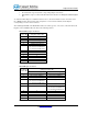
CANpro/104 User Manual J3B Position 1 2 3 4 Function Jumper Installed Jumper Removed Mem Addr[16] or I/O Addr[9] = 1 Mem Addr[16] or I/O Addr[9] = 0 Mem Addr[15] or I/O Addr[8] = 1 Mem Addr[15] or I/O Addr[8] = 0 Mem Addr[14] = 1 Mem Addr[14] = 0 or or I/O Addr[7] = 1 (BasicCAN mode only) I/O Addr[7] = 0 (BasicCAN mode only) Mem Addr[13] = 1 Mem Addr[13] = 0 or or I/O Addr[6] = 1 (BasicCAN mode only) I/O Addr[6] = 0 (BasicCAN mode only) Memory Space Enable Bit-2 [Note 1] Memory Space Enable Bit-1 [Note 1
CANpro/104 User Manual Hardware Installation – Rev A & B Before you begin, take a minute to ensure that your package includes the required components that should have shipped with your CANpro/104. ● ● One CANpro/104 CAN controller board One CD containing documentation If any of these components is missing, contact Connect Tech (See Contact Details) or your reseller.
CANpro/104 User Manual Interrupts and Memory I/O Range Selection CANpro/104’s interrupt lines and I/O ranges are jumper assignable. Interrupt Selection J1 and J2 are used for interrupt selection. Interrupt selection for the first CAN controller is achieved via the upper and centre rows of pins on the connector. The lower and center rows of pins allow selection of interrupts for the second CAN controller. Please refer to Figure 1 to locate jumper blocks J1 and J2.
CANpro/104 User Manual Address Mode and Range Selection The first five jumper locations of jumper block J3 are used for board address selection. The first jumper location (Addr Mode) selects the number of address bits to use for the decoding of the board address. The next four jumpers configure the actual board address. If you intend to configure both of the board’s controllers in BasicCAN mode, install a jumper in the Addr Mode location.
CANpro/104 User Manual Interrupt Sharing Jumper block J3 also plays a part in the interrupt sharing. PC/104 supports the sharing of an interrupt between multiple cards. For example, two separate CANpro/104 cards are able to share the same interrupt across all four controllers. To accomplish interrupt sharing, the following steps must be taken: All cards that share the same interrupt, but are not actively asserting an interrupt, must tri-state their outputs.
CANpro/104 User Manual Other On-board Jumper Selection Near each I/O connector a 2x2 jumper block (either J4 or J5) will allow the configuration of both bus termination and slew rate limiting for the transceiver. J4 configures options for CAN controller 0, while J5 configures options for CAN controller 1. Installing a jumper on the first location of J4 or J5 (the gray area above) will enable a 120 Ohm termination resistor across the CAN-H and CAN-L lines.
CANpro/104 User Manual Connector Pinouts Table 25: DB-9 Cable Connector Pinouts Pin No. 1 2 3 4 5 6 7 8 9 Signal +5V CAN-L CAN GND (isolated or non) N/C N/C CAN GND (isolated or non) CAN-H N/C +5V Male DB-9 Connector 1 5 9 6 For boards populated with right angled 2x5 0.100” headers, cable CAG104 will break out from the onboard 2x5 header to a DB-9 connector. Table 26: 10-pin Header Pinouts Pin No.
CANpro/104 User Manual Specifications Operating Environment Storage temperature: Operating temperature: Humidity: -40 C to 125 C -40 C to 85 C 95%, non-condensing Power Requirements +5 VDC @ 500mA (maximum) 380 mA (minimum) NOTE: Power output on CAN connectors may draw up to an additional 1A per port (non-isolated models). 190 mA per port (isolated models) given 150mA current draw in the +5V output.
CANpro/104 User Manual Limited Lifetime Warranty Connect Tech Inc. provides a Lifetime Warranty for all Connect Tech Inc. products. Should this product, in Connect Tech Inc.'s opinion, fail to be in good working order during the warranty period, Connect Tech Inc. will, at its option, repair or replace this product at no charge, provided that the product has not been subjected to abuse, misuse, accident, disaster or non Connect Tech Inc. authorized modification or repair.