USER MANUAL CANpro/104-Plus Opto CTIM-00052 Revision 0.
CANpro/104-Plus Opto User Manual Copyright Notice The information contained in this document is subject to change without notice. Connect Tech Inc. shall not be liable for errors contained herein or for incidental consequential damages in connection with the furnishing, performance, or use of this material. This document contains proprietary information that is protected by copyright. All rights are reserved.
CANpro/104-Plus Opto User Manual Table of Contents Copyright Notice ................................................................................................................................................ 2 Trademark Acknowledgement ............................................................................................................................ 2 Revision History ..............................................................................................................................
CANpro/104-Plus Opto User Manual Introduction CANpro/104-Plus Opto combines the power of two independent NXP SJA1000 CAN controllers with 3kV optical isolation to provide maximum protection for industrial control applications exposed to harsh conditions. Based on the PCI bus and a PCI-104 form factor, CANpro/104-Plus Opto frees up valuable I/O space for greater flexibility in your embedded system. Features ● ● ● ● ● ● ● ● ● ● ● ● ● ● Two independent, industry standard NXP SJA1000 CAN controllers (2.
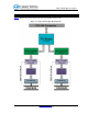
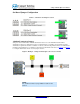
CANpro/104-Plus Opto User Manual CANpro/104-Plus Opto Diagrams Figure 1 illustrates the location of each component on the CANpro/104-Plus Opto. Figure 1: CANpro/104-Plus Opto Block Diagram 5 www.connecttech.com 800-426-8979 | 519-836-1291 CTIM-00052 Revision 0.
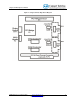
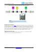
CANpro/104-Plus Opto User Manual Figure 2: CANpro/104-Plus Opto Board Diagram CTIM-00052 Revision 0.00 4/23/2009 www.connecttech.
CANpro/104-Plus Opto User Manual Hardware Installation Before You Begin Before you begin, take a minute to ensure that your package includes the required components that should have shipped with your CANpro/104-Plus Opto. ● ● One CANpro/104-Plus Opto CAN controller board One CD containing documentation If anything is missing, contact Connect Tech or your reseller.
CANpro/104-Plus Opto User Manual PCI Interrupt, Clock and ID Selection The following PCI signals, (INTA#, INTB# INTC# INTD#), (CLK0, CLK1, CLK2, CLK3), (IDSEL0, IDSEL1, IDSEL2, IDSEL3), are selected by using the Rotary Switch on the CANpro/104-Plus Opto board (RSW1). Selections need to match the stack location of the CANpro/104-Plus Opto in your PC/104-Plus stack. See Table 1 below for more details.
CANpro/104-Plus Opto User Manual On-Board Jumper Configuration Figure 3: CAN Ports and Jumper Locations 120 Ohm Termination Jumpers Jumpers J1 and J4 will enable a 120 Ohm termination resistor across the CAN-H and CAN-L lines. Termination is always recommended for improved signal integrity, especially for long transmission lines. Termination requirements should be evaluated on a case by case basis.
CANpro/104-Plus Opto User Manual Figure 5: Example CANpro/104-Plus Opto in the middle of the CAN bus NOTE: The 120 Ohm termination jumper does not need to be installed in this situation. Slew Rate Control Jumpers Installing a jumper on J2 or J5 (see Figure 3) will disable slew rate limiting for the associated CAN port. Slew rate limiting will reduce the emitted switching noise that is sent out onto the CAN bus lines and radiated from those lines.
CANpro/104-Plus Opto User Manual Connector Pinouts Table 2: DB-9 Cable Connector Pinouts Pin No. 1 2 3 4 5 6 7 8 9 Signal +5V CAN-L CAN GND (isolated or non) N/C N/C CAN GND (isolated or non) CAN-H N/C +5V Male DB-9 Connector 1 5 9 6 Boards that are populated with right angled 2x5 0.100” headers will include a cable (CAG104) that will break out from the on-board 2x5 header to a DB-9 connector. Table 3: 10-pin Header Pinouts Pin No.
CANpro/104-Plus Opto User Manual Software Configuration The information provided below is intended for advanced users and developers that wish to create their own custom drivers. Typical CANpro/104-Plus Opto users will used the driver provided by Connect Tech.
CANpro/104-Plus Opto User Manual Table 4: CAN Controller #1 (BasicCAN) OPERATING MODE 0x000 0x001 0x002 0x003 0x004 0x005 0x006 0x007 0x008 0x009 0x00A 0x00B 0x00C 0x00D 0x00E 0x00F 0x010 0x011 0x012 0x013 0x014 0x015 0x016 0x017 0x018 0x019 0x01A 0x01B 0x01C 0x01D 0x01E 0x01F ...
CANpro/104-Plus Opto User Manual Table 5: CAN Controller #2 (BasicCAN) OPERATING MODE 0x100 0x101 0x102 0x103 0x104 0x105 0x106 0x107 0x108 0x109 0x10A 0x10B 0x10C 0x10D 0x10E 0x10F 0x110 0x111 0x112 0x113 0x114 0x115 0x116 0x117 0x118 0x119 0x11A 0x11B 0x11C 0x11D 0x11E 0x11F ...
CANpro/104-Plus Opto User Manual Table 6: CAN Controller #1 (PeliCAN) Local Address 0x000 0x001 0x002 0x003 0x004 0x005 0x006 0x007 0x008 0x009 0x00A 0x00B 0x00C 0x00D 0x00E 0x00F 0x010 0x011 0x012 0x013 0x014 0x015 0x016 0x017 0x018 0x019 0x01A 0x01B 0x01C 0x01D 0x01E 0x01F 0x020 0x021 0x022 0x023 ... 0x06D 0x06E 0x06F 0x070 0x071 ...
CANpro/104-Plus Opto User Manual Table 7: CAN Controller #2 (PeliCAN) Local Address 0x100 0x101 0x102 0x103 0x104 0x105 0x106 0x107 0x108 0x109 0x10A 0x10B 0x10C 0x10D 0x10E 0x10F 0x110 0x111 0x112 0x113 0x114 0x115 0x116 0x117 0x118 0x119 0x11A 0x11B 0x11C 0x11D 0x11E 0x11F 0x120 0x121 0x122 0x123 ... 0x16D 0x16E 0x16F 0x170 0x171 ...
CANpro/104-Plus Opto User Manual CAN Controller Interrupts Each CAN controller is tied to a local interrupt on the PLX9030 which is then forwarded to a single interrupt on the PCI bus. Access to the PLX9030 interrupt control/status register can be done by accessing the INTCSR register at offset 4Ch from the PCI base address of the CANpro/104-Plus Opto. This diagram is taken from the PLX9030 Data Book v1.4. GPIO Details GPIO Header CANpro/104-Plus Opto includes a 10-pin header with 8-bits of 3.
CANpro/104-Plus Opto User Manual GPIO Control and Addressing GPIO pins on the CANpro/104-Plus Opto are controlled via the GPIOC register within the PLX 9030. The register is located at offset 0x54 from the PLX9030 PCI Base Address. The CANpro/104-Plus Opto ships with all GPIO pins set up as a data output pin by default. This diagram is taken from the PLX9030 Data Book v1.4. 19 www.connecttech.com 800-426-8979 | 519-836-1291 CTIM-00052 Revision 0.
CANpro/104-Plus Opto User Manual Specifications Operating Environment Storage temperature: -40 C to 125 C Operating temperature: -40 C to 85 C Humidity: 95%, non-condensing Power Requirements +5 VDC @ 500mA (maximum) 380 mA (minimum) NOTE: External power output pins on each CAN port is limited up to 125 mA per port . PC Bus Interface PC/104-Plus Optical/Power Isolation 3kV for each CAN port from the host system and other isolated CAN ports. Dimensions Compliant to PC/104-Plus specification 2.
CANpro/104-Plus Opto User Manual Certification Certification for CANpro/104-Plus Opto The CANpro/104-Plus Opto product family is to be included into a device ultimately subject to FCC, DOC/IC, and CE certification. The customer is responsible for bringing the completed device into compliance prior to resale. Connect Tech has designed CANpro/104-Plus Opto with EMI and EMC considerations such as: Ground and power planes Controlled slew-rate signals EMI/EMC reducing PCB layout 21 www.connecttech.
CANpro/104-Plus Opto User Manual Limited Lifetime Warranty Connect Tech Inc. provides a Lifetime Warranty for all Connect Tech Inc. products. Should this product, in Connect Tech Inc.'s opinion, fail to be in good working order during the warranty period, Connect Tech Inc. will, at its option, repair or replace this product at no charge, provided that the product has not been subjected to abuse, misuse, accident, disaster or non Connect Tech Inc. authorized modification or repair.