
User manual
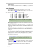
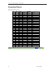
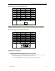
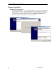
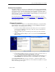

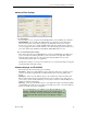
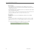
Table Of Contents
- Limited Lifetime Warranty
- Copyright Notice
- Trademark Acknowledgment
- Contact Information
- BlueStorm/Express Installation Overview
- Hardware Configuration
- Interrupts and Memory Address Selection
- RS-232 Electrical Interface
- RS-422/485 Electrical Interface
- Jumper Block Settings
- Tri-state Operation
- Installing the BlueStorm/Express into your system
- Software First Installation
- Hardware First Installation
- Windows XP Installation
- Port Settings
- Advanced Port Settings
- Software Settings for RS-422/485
- Specifications
Connect Tech BlueStorm/Express User Manual
Revision 0.02
15
Table 4: RJ-45 pinouts for BlueStorm/Express Opto
Pin No.
RS-232
Signal
Direction
RS-422/485
Signal
Direction
1 N/C no connect RTS (-) output
2 N/C input RxD (+) input
3 RTS output RTS (+) output
4 SG signal gnd SR signal ref.
5 TxD output TxD (+) output
6 RxD input RxD (-) input
7 Gnd ground Gnd. ground
8 CTS input CTS (+) input
9 N/C no connect TxD (-) output
10 N/C no connect CTS (-) input
RJ-45 connector
1
10
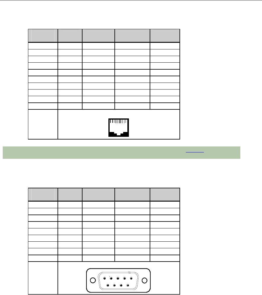
Cable CAGRJ4509 will send the signals to four DB-9 male connectors. See Table 5 for the DB-9
pinouts
Table 5: DB-9 male pinouts for BlueStorm/Express Opto
Pin No.
RS-232
Signal
Direction
RS-422/485
Signal
Direction
1 N/C no connect RxD (+) input
2 RxD input RxD (-) input
3 TxD output TxD (+) output
4 N/C no connect TxD (-) output
5 SG signal gnd SR signal ref.
6 N/C no connect CTS (-) input
7 RTS output RTS (+) output
8 CTS input CTS (+) input
9 N/C no connect RTS (-) output
Male DB
-
9 Connector
1
5
6
9
Hardware Installation
Installing the BlueStorm/Express into your system
Turn off the power to your computer and open it to expose the expansion slots (consult your
system’s documentation for more information on this procedure).
Choose an available PCI Express position and gently press the card into the slot.