
User manual
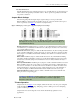
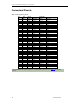
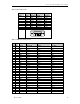
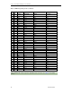
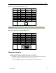

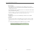
Table Of Contents
- Limited Lifetime Warranty
- Copyright Notice
- Trademark Acknowledgment
- Contact Information
- BlueStorm/Express Installation Overview
- Hardware Configuration
- Interrupts and Memory Address Selection
- RS-232 Electrical Interface
- RS-422/485 Electrical Interface
- Jumper Block Settings
- Tri-state Operation
- Installing the BlueStorm/Express into your system
- Software First Installation
- Hardware First Installation
- Windows XP Installation
- Port Settings
- Advanced Port Settings
- Software Settings for RS-422/485
- Specifications
Connect Tech BlueStorm/Express User Manual
Revision 0.02
11
Line Bias/Termination
The RS-422/485 transceivers, transmit and receive, are optionally biased to produce a line level
mark condition through jumper selectable resistors. These options are typically used in multi-
drop 4-wire connections.
Jumper Block Settings
The following jumper block diagram depicts typical settings on a four-port selectable
BlueStorm/Express. Jumper blocks JA and JB control ports 1 and 2, JC and JD control ports 3
and 4, respectively. (See Figure 1 for locations of jumper blocks.)
Figure 4: Example of various port configuration jumper block settings
In this example, Port 1(JA) is set to RS-232, Port 2 (JB) is set to RS-422/485
half duplex, Port 3 (JC) is set to RS-422/485 full duplex, and Port 4 (JD) is set
to RS-422/485 multi-drop.
RS-485 Selection: Install this jumper to configure a port for RS-422/485 mode. If the jumper is
not installed, the port will function in RS-232 mode. (All jumpers should be removed from any
port operating in RS-232 mode.)
TxD Control: Install this jumper to enable the RS-485 transmitter only when sending data. This
mode is useful for half-duplex operation when only one device is allowed to send data at a time.
If the jumper is not installed, the transmitter will always drive the line to an idle state when not
sending data.
RxD control: Install this jumper to enable the RS-485 receiver only when NOT transmitting
data. This is useful for half-duplex operation to prevent the transmitting device from receiving
the data it has sent. If this jumper is not installed, the receiver is always enabled and ready to
receive data.
RxD ± Termination/Bias: Install this pair of jumpers to enable a 150 Ohm terminator across the
RxD+ and RxD- pins for the corresponding port. A biasing network is also enabled that drives
the receiver to an inactive or safe mode. The receiver can still receive data from another device
and the biasing helps to prevent the reception of data generated by noise on the transmission
line. The two jumpers for RxD termination/bias must be installed and removed as a pair.
TxD ± Termination: Install this jumper to enable a 150 Ohm resistor across the TxD+ and
TxD- pins of the corresponding port.
Half Duplex and Multi-drop modes require you to select the appropriate mode
via software. Please refer to the readme.txt files found in the appropriate
directories on the CD.
Tri-state Operation
Jumper block J2 (see Figure 1 for an example) enables Tx tri-state on boot for ports configured
as RS-485 half duplex or multi-drop. Jumpering position 1 enables ports 1 and 2. Jumpering
position 2 enables ports 3 and 4.
Jumper block J1 is used in diagnostic modes and should be left unpopulated for most
applications.