Blue Heat/PCI PCI Serial Communications User Manual Connect Tech Inc 42 Arrow Road Guelph, Ontario N1K 1S6 Tel: 519-836-1291 Toll: 800-426-8979 (North America only) Fax: 519-836-4878 Email: sales@connecttech.com support@connecttech.com URL: www.connecttech.com CTIM-00311, Revision 0.
Blue Heat/PCI User’s Manual, Connect Tech Inc. Limited Lifetime Warranty Connect Tech Inc. provides a Lifetime Warranty for all Connect Tech Inc. products. Should this product, in Connect Tech Inc.'s opinion, fail to be in good working order during the warranty period, Connect Tech Inc. will, at its option, repair or replace this product at no charge, provided that the product has not been subjected to abuse, misuse, accident, disaster or non Connect Tech Inc. authorized modification or repair.
Blue Heat/PCI User’s Manual, Connect Tech Inc. Table of Contents Limited Lifetime Warranty ..............................................................................................................................2 Copyright Notice .............................................................................................................................................2 Trademark Acknowledgment............................................................................................................
Blue Heat/PCI User’s Manual, Connect Tech Inc. Power Requirements ................................................................................................45 Communications ......................................................................................................45 Control Signals ........................................................................................................45 Dimensions .............................................................................................
Blue Heat/PCI User’s Manual, Connect Tech Inc. Customer Support Overview If you experience difficulties after reading the manual and/or using the product, contact the Connect Tech reseller from which you purchased the product. In most cases the reseller can help you with product installation and difficulties. In the event that the reseller is unable to resolve your problem, our highly qualified support staff can assist you.
Blue Heat/PCI User’s Manual, Connect Tech Inc. Certification Blue Heat/PCI Blue Heat/PCI RS-422/485 Blue Heat/PCI RJ-11 Blue Heat/PCI Opto; Opto RS-422/485 Blue Heat/PCI CL Universal Blue Heat/PCI RS-422/485 Connect Tech Inc. declares that the product(s) covered by the contents of this manual have been tested and found compliant with the below listed standards as required by the Electromagnetic Compatibility (EMC) Directive for General Immunity Compliance, EN 50 0082.
Blue Heat/PCI User’s Manual, Connect Tech Inc. Introduction The Blue Heat/PCI family of adapters includes the Blue Heat/PCI RS-232, RS-422/485, RJ-11, Opto, 20mA CL and Universal Blue Heat/PCI RS-422/485. provide high speed interfaces, allowing you to connect up to eight serial devices through one expansion slot.
Blue Heat/PCI User’s Manual, Connect Tech Inc. ● ● ● Revision 0.11 Six RJ-11 connectors provide +12 VDC or +5 VDC output (factory installed) on pin 6 with a current limit of 300 mA total for +12 VDC and 1A total for +5 VDC. (Blue Heat/PCI RJ-11 model) System requirements are one 32-bit 5V PCI bus compatible slot (Blue Heat/PCI, RS-422/485, RJ-11, Opto, Opto RS-422/485, 20mA CL, Universal Blue Heat/PCI RS-422/485 adapters) or a 3.
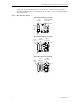
Blue Heat/PCI User’s Manual, Connect Tech Inc. Figures 1 through 7 show the locations of various hardware components found on the Blue Heat/PCI, RS-422/485, Opto, Opto RS-422/485, RJ-11, 20mA CL and Universal Blue Heat/PCI RS-422/485 models.
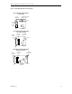
Blue Heat/PCI User’s Manual, Connect Tech Inc. Figure 2: Blue Heat/PCI RS-422/485 adapters Blue Heat/PCI RS-422/485 adapter (2 port model) 16C864 Quad UART (2 Ports Used) Surge Suppression CPLD DB-9 Port 2 DB-9 Port 1 PCI Bridge Blue Heat/PCI RS-422/485 adapter (4 port & 2+2 models) DB-37 Connector Surge Suppression 16C864 Quad UART CPLD PCI Bridge Blue Heat-8/PCI RS-422/485 adapter (8 port & 4+4 models) DB-78 Connector Surge Suppression PCI Bridge Revision 0.
Blue Heat/PCI User’s Manual, Connect Tech Inc. Figure 3: Universal Blue Heat/PCI RS-422/485 adapters Universal Blue Heat/PCI RS-422/485 (8 port & 4+4 models) DB-78 Connector Surge Suppression J1 – Tri-state control 16C864 Quad UARTs CPLD PCI Bridge Figure 4: Blue Heat/PCI RS-422/485 adapter (6+2 model) Blue Heat/PCI RS-422/485 adapter (6+2 model) Tri-state control Line bias termination J1 through J13 16C864 Quad UARTs CPLD DB-78 Connector Surge Suppression 11 PCI Bridge Revision 0.
Blue Heat/PCI User’s Manual, Connect Tech Inc.
Blue Heat/PCI User’s Manual, Connect Tech Inc. Figure 7: Blue Heat/PCI adapter Blue Heat/PCI CL adapter Current Source Voltage Select J1, J2, J3, J4, J5, J6, J7, J8 DB-78 Connector 16C654 Quad UARTs PCI Bridge CPLD You can combine different Blue Heat/PCI and Universal Blue Heat/PCI RS-422/485 adapters in a single computer to accommodate both small and large multi-channel applications. Figure 8 below represents a sample configuration for a system requiring 20 ports.
Blue Heat/PCI User’s Manual, Connect Tech Inc. Hardware Installation Hardware installation involves configuration of the following Blue Heat/PCI products: The Blue Heat/PCI; RS-422/485; Opto; Opto RS-422/485; 20mA CL; RJ-11 and Universal Blue Heat/PCI RS-422/485 adapters Note: Please see the Software Installation section for installation of your Blue Heat/PCI or Universal Blue Heat/PCI board under certain operating systems.
Blue Heat/PCI User’s Manual, Connect Tech Inc. If this occurs, the driver will signal that a given resource has not been assigned, which requires the user to assign system resources manually. Remove the assignments for ISA devices with the BIOS setup and then reboot the computer. After reboot, determine with the BIOS setup utility what resources have been assigned to the PCI devices and then do manual assignments of free resources to ISA devices. Reboot your system.
Blue Heat/PCI User’s Manual, Connect Tech Inc. Software Installation Introduction Blue Heat/PCI boards are standard multi-port serial adapters that utilize 16C654, 16C864 or 16C2850 UARTS. In many cases, users have software that will interface directly to the Blue Heat/PCI boards. Many operating systems come with handlers to control access to multiple 8250 style UARTS.
Blue Heat/PCI User’s Manual, Connect Tech Inc.
Blue Heat/PCI User’s Manual, Connect Tech Inc. Power Requirements (continued) Universal Blue Heat/PCI RS-422/485 (8 port model) +3 VDC ±5% @ 100mA (typical) +5 VDC ±5% @ 460mA (typical) PCI Bus Interface One One 32 bit, 5V PCI slot 32 bit 3.
Blue Heat/PCI User’s Manual, Connect Tech Inc. Control Signals (continued) Blue Heat/PCI CL Models: TxD; RxD • 20mA Surge Suppression Blue Heat Models: • 500 watts, 8 x 20 µS (EN61000-4-2/3/4 compatible) on every signal of every port. Blue Heat/PCI RS-422/485; Universal Blue Heat/PCI RS-422/485 Models: • TransGuard Transient Voltage Suppression, able to withstand multiple strikes on every signal of every port. • Transient Energy dissipation 0.
Blue Heat/PCI User’s Manual, Connect Tech Inc. Dimensions (continued) Blue Heat/PCI Opto; Opto RS-422/485 (2 & 4 port models) Length: 19.50 cm Width: 1.50 cm Height: 9.50 cm Weight: 0.12 kg Blue Heat/PCI 20mA CL Length: 18.00 cm Height: 10.50 cm Width: Weight: 1.50 cm 0.12 kg Blue Heat/PCI RS-422/485 Length: 10.00 cm Width: Height: 10.50 cm Weight: 1.50 cm 0.
Blue Heat/PCI User’s Manual, Connect Tech Inc.
Blue Heat/PCI User’s Manual, Connect Tech Inc. Table 1: DB-9 pinouts for Blue Heat/PCI RS-232, 422/485 models, Universal Blue Heat/PCI RS-422/485 Pin No. 1 2 3 4 5 6 7 8 9 RS-232 Signal DCD RxD TxD DTR SG DSR RTS CTS RI Direction input input output output signal gnd input output input input RS-422/485 Signal RxD B(+) TxD B(+) TxD A(-) RxD A(-) SR CTS A(-) RTS A(-) RTS B(+) CTS B(+) Direction input output output input signal ref.
Blue Heat/PCI User’s Manual, Connect Tech Inc. Table 3: RJ-45 pinouts for the Blue Heat/PCI Opto Pin No. 1 2 3 4 5 6 7 8 9 10 RS-232 Signal N/C N/C RTS SG TxD RxD Gnd CTS N/C N/C RS-422/485 Signal RTS (-) RxD (+) RTS (+) SR TxD (+) RxD (-) Gnd. CTS (+) TxD (-) CTS (-) Direction no connect input output signal gnd output input ground input no connect no connect Direction output input output signal ref.
Blue Heat/PCI User’s Manual, Connect Tech Inc. Table 5: Blue Heat/PCI RJ-11 pinouts DB-9 Pin No. 1 2 3 4 5 6 7 8 9 RS-232 Signal DCD RxD TxD DTR SG DSR RTS CTS RI Direction input input output output signal ground input output input input RJ-11 Pin No.
Blue Heat/PCI User’s Manual, Connect Tech Inc. Table 7: DB-37 pinouts for Blue Heat/PCI RS-232 and RS-422/485 models Pin Port No. No.
Blue Heat/PCI User’s Manual, Connect Tech Inc. Table 8: DB-78 pinouts for Blue Heat/PCI RS-232, RS-422/485, Universal Blue Heat/PCI RS-422/485 Pin No. 1 2 3 4 5 6 7 8 9 10 11 12 13 14 15 16 17 18 19 20 21 22 23 24 25 26 27 28 29 30 31 32 33 34 35 36 37 38 39 Port No.
Blue Heat/PCI User’s Manual, Connect Tech Inc. Table 8 (cont.): DB-78 pinouts – Blue Heat/PCI; RS-422/485; 20mA CL; Universal Blue Heat/PCI RS-422/485 Pin Port RS-232 Signal No. No. Signal Direction 40 1 RTS output 41 1 CTS input 42 1 DSR input 43 1 RI input 44 1 SG signal gnd. 45 2 RTS output 46 2 CTS input 47 2 DSR input 48 2 RI input 49 3 RTS output 50 3 CTS input 51 3 DSR input 52 3 RI input 53 3 SG signal gnd.
Blue Heat/PCI User’s Manual, Connect Tech Inc. Connector Box Pinouts You may order the Blue Heat/PCI (8 port model), Blue Heat/PCI RS-422/485 (8 port, 4+4 and 6+2 models) and Blue Heat/PCI CL with an external I/O Box or the RJ-45 Connector Plug option. The I/O Box option comes with a metal bracket that can be mounted on a wall or other surface. When you receive the I/O Box, this bracket is clipped on to the back of the connector box.
Blue Heat/PCI User’s Manual, Connect Tech Inc. Figure 9: Blue Heat/PCI, RS-422/485, 20mA CL and Universal Blue Heat/PCI RS-422/485 I/O Box External I/O Box (p/n: IOB08DB9 or IOB08DB9V1) Male DB-9 connectors Mounting bracket DB-78 connector Table 9: DB-9 pinouts for Blue Heat/PCI RS-232, RS-422/485, 20mA CL and Universal Blue Heat/PCI RS-422/485 I/O Box Pin No. 1 2 3 4 5 6 7 8 9 RS-232 Signal DCD RxD TxD DTR SG DSR RTS CTS RI Direction input input output output signal gnd.
Blue Heat/PCI User’s Manual, Connect Tech Inc. Figure 10: RJ-45 Connector Plug 1 2 3 4 8 7 6 5 Table 10: RJ-45 pinouts, RJ-45 connector plug Pin No. RS-232 Signal Direction RS-422/485 Signal Direction 20mA 1 RI input CTS (+) input RxD Source 2 3 4 5 6 7 8 9 10 DSR RTS SG TxD RxD Gnd CTS DTR DCD input output signal gnd. output input ground input output input CTS (-) RTS (-) FG TxD (-) TxD (+) Gnd RTS (+) RxD (-) RxD (+) input output frame gnd.
Blue Heat/PCI User’s Manual, Connect Tech Inc. Appendix C: RS-422/485 Line Interface For information on how to configure your RS-422/485 interface, find your specific Blue Heat/PCI model below: Blue Heat/PCI RS-422/485 You can order the Blue Heat/PCI RS-422/485 adapter with all ports RS-422/485 or a combination of RS-422/485 and RS-232. The RS-422/485 electrical interface is a reliable highspeed serial link that offers superior noise immunity and multi-drop network connectivity.
Blue Heat/PCI User’s Manual, Connect Tech Inc. Blue Heat/PCI RS-422/485 (6+2 model) The Blue Heat/PCI RS-422/485 (6+2 model) offers full RS-422/485 support in hardware like the other Blue Heat/PCI RS-422/485 models. The modes include full duplex, half duplex, and multidrop slave. The Blue Heat/PCI RS-422/485 (6+2 model) offers the following additional functionality. Tri-state Control The Blue Heat/PCI RS-422/485 6+2 model allows you to tri-state the line drivers on power up.
Blue Heat/PCI User’s Manual, Connect Tech Inc. Figure 11: Partial schematic: Blue Heat/PCI RS-422/485; Universal Blue Heat/PCI RS-422-485 Blue Heat/PCI RS-422/485 Universal Blue Heat/PCI RS-422/485 RS-422/485 Line Bias/Termination Blue Heat/PCI RS-422/485 (6+2 model) RS-422/485 Line Bias/Termination TxD + TxD + TxD TxD 150 Ω J2, J8 TxD - TxD - +5 V 1.8K Ω RxD +5 V 1.8K Ω RxD + RxD 150 Ω 150 Ω J5, J11 RxD 1.8K Ω 16C864 UART RxD + J4, J10 RxD 1.
Blue Heat/PCI User’s Manual, Connect Tech Inc. Example 1 The following example shows the settings on J1 to tri-state the line drivers upon power up of the Blue Heat/PCI RS-422/485 adapter (6+2 model).
Blue Heat/PCI User’s Manual, Connect Tech Inc. Blue Heat/PCI Opto and Opto RS-422/485 The Blue Heat/PCI Opto ships with all ports jumper selectable for RS-232 or RS-422/485. The Blue Heat/PCI Opto RS-422/485 ships with all ports RS-422/485 only. Both the Blue Heat/PCI Opto and the Blue Heat/PCI Opto RS-422/485 offer full RS-422/485 support in hardware with three modes: Full Duplex, Half Duplex, and Multi-drop Slave. You enable these modes via software.
Blue Heat/PCI User’s Manual, Connect Tech Inc. Half Duplex Mode In this mode the TxD line driver is enabled only when data is transmitted and RxD is disabled when data is being transmitted. This mode is typically used in either point to point "2 wire" connections OR in multi-drop "2 wire" bus connections. To enable this mode for a port you must jumper positions 7 and 8 on the appropriate jumper blocks JA, JB, JC, JD. These jumpers short TxD – to RxD – and TxD + to RxD +.
Blue Heat/PCI User’s Manual, Connect Tech Inc. Line/Bias Termination You can use jumper blocks JA, JB, JC and JD to terminate and bias TxD ±, RxD ±, RTS ±, and CTS ± on the individual RS-422/485 ports through jumper selectable 150 Ω fixed resistors. Please refer to Figure 12 for a partial schematic of the RS-422/485 circuit for the Blue Heat/PCI Opto and Figure 6 for the locations of JA, JB, JC, and JD.
Blue Heat/PCI User’s Manual, Connect Tech Inc. RS-422/485 Cable Wiring You can wire Blue Heat/PCI RS-422/485, Opto RS-422/485 and Universal Blue Heat/PCI RS-422/485 adapters in various ways to communicate with RS-422/485 peripherals. This section describes a few examples of RS-422/485 cabling schemes. Figure 13 below describes a 4 wire cabling scheme between a port on the Blue Heat/PCI RS-422/485, Opto, Opto RS-422/485 or Universal Blue Heat/PCI RS-422/485 adapter to a port on the RS-422/485 peripheral.
Blue Heat/PCI User’s Manual, Connect Tech Inc. Figure 14 below describes a 2 wire cabling scheme between a port on the Blue Heat/PCI RS-422/485, Opto, Opto RS-422/485 or Universal Blue Heat/PCI RS-422/485 adapter to a port on the RS-422/485 peripheral.
Blue Heat/PCI User’s Manual, Connect Tech Inc. Appendix D: 20mA Current Loop Line Interface Blue Heat/PCI 20mA CL The Blue Heat/PCI CL offers a 20mA Current Loop active or passive electrical interface. For each port there is an optically isolated receiver, an optically isolated transmitter and a 20mA current source. Optical isolation is functional in passive mode only. See Figure 15 for the schematic of the 20mA Current Loop module.
Blue Heat/PCI User’s Manual, Connect Tech Inc. Current Source/Voltage Selection When using the current source in a loop with low resistance, the transistor will run hot. This can be avoided by increasing the loop resistance. The calculation for Maximum Loop Resistance(RL ) is: Max RL = VS - (S × VD ) 0.
Blue Heat/PCI User’s Manual, Connect Tech Inc. Current Loop Cable Wiring You can wire Blue Heat/PCI CL adapters in various ways to communicate with 20mA Current Loop peripherals. A few examples of Current Loop cabling schemes follow. Figure 16 below depicts a 4 wire cabling scheme between a port on the Blue Heat/PCI CL adapter to another port on the Blue Heat/PCI CL adapter.
Blue Heat/PCI User’s Manual, Connect Tech Inc. 43 Revision 0.
Blue Heat/PCI User’s Manual, Connect Tech Inc. Appendix E: Blue Heat/PCI PTM model Blue Heat/PCI PTM Adapter The Blue Heat/PCI Pass Through Mux (PTM) adapter offers two asynchronous RS-232 serial ports with Monitor Pass Through and Intercept Pass Through capabilities. In Monitor mode the Blue Heat/PCI PTM adapter allows you to monitor and pass through the data from a device connected to one serial port to a device connected to the other serial port.
Blue Heat/PCI User’s Manual, Connect Tech Inc. Specifications for the Blue Heat/PCI PTM Power Requirements Blue Heat/PCI PTM +5 VDC ±5% @ 360mA (typical) ±12 VDC ±10% @ 32mA (typical) Communications Blue Heat/PCI PTM o Communication controllers: 16C2850 dual UARTs c/w 128 byte TxD/RxD FIFO buffers o Programmable baud rate generator: 50 BPS to 921.6 KBPS on all ports Control Signals Blue Heat/PCI PTM DTR; DSR; RTS; CTS; RI; TxD; RxD; DCD Dimensions Blue Heat/PCI PTM Length: 12.60 cm Height: 1.
Blue Heat/PCI User’s Manual, Connect Tech Inc. Connectors/Pinouts Table 11 shows the pinouts for the Blue Heat-2/PCI PTM connectors. Figure 18 and Figure 19 depict the circuit connections on the Blue Heat/PTM for Monitor Pass Through and Intercept Pass Through Modes. Technical Tip: Please ensure that you terminate signals if your application does not use them. Failure to do so may result in a loss of a performance on your Blue Heat/PCI PTM adapter.
Blue Heat/PCI User’s Manual, Connect Tech Inc.