CS4000 AND CS4001 USERS MANUAL FM HANDHELD TRANCEIVER CONNECT SYSTEMS INCORPORATED 1802 Eastman Ave., Suite 116 Ventura CA 93003 VERSION 1.
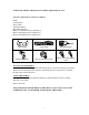
GUIDE FOR THOSE THAT DO NOT LIKE TO READ MANUALS You have eight items in your box as follows: Radio Fixed Bracket Power Cable Hand Microphone Microphone Hanger M4*10 Combination Screw (quantity 4) M4*16 Self-tapping Screw (quantity 2) M5*16 Self-tapping Screw (quantity 4) Fixed bracket Power Cable Hand Microphone Microphone Hanger M4*10 Combination Screw M5*16 / M4*16 Self-tapping Screw SETTING UP THE RADIO Please use the service of a qualified radio technician as it involves attaching an external an
Thank You We are very grateful for you purchasing the Connect Systems Inc. brand professional two-way radio. This radio incorporates the latest technology and can bring great convenience to your life and work. The quality and function of this radio will meet your demands for reliable communication.
Warning on Danger of Radio Frequency and Magnetic Energy The Model CS4000 and CS4001 generates both radio frequency energy and magnetic energy while transmitting. Any transmitter has the potential to cause heating and other thermal effects in your body. The amount of heating and other thermal effects is determined by the power out from the radio and the distance from the body.
FCC Warnings This equipment generates or uses radio frequency energy. Changes or modifications to this equipment may cause harmful interference unless the modifications are expressly approved in the instruction manual. The user could lose the authority to operate this equipment if an unauthorized change or modification is made. This equipment has been tested and found to comply with the limits for a Class B digital device, pursuant to Part 15 of the FCC rules.
INSTRUCTIONS FOR THE RADIO TECHNICIAN Connection of Power Cable Check whether there is a hole for the power cable on the insulating board. If not, bore the board with the suitable drill bit and fix a rubber grommet on it. Have the cable pass through the insulating board into the car engine. Connect the red conductor to the positive terminal of the Battery or an equivalent point and connect the black conductor to the negative terminal of the battery or an equivalent point.
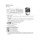
Radio Overview Front Panel ⑾ ( 1) power button Press this button for a long time (more than 1.5 seconds) to start or close the radio. ( 2) LED indicator The red indicator will light when it transmitting. The green indicator will light when it receiving. The indicator will flicker and give an orange light when it receives DTMF, 2Tone, or MDC signal indicating some selective call feature. The red indicator flashes in the scanning process.
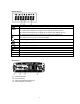
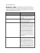
Display Screen Display Description It means the receiving signal strength. 4 lines mean the strongest signal. Transmission power level ”L” means the transmission of signal for the radio at the lower power; ”M” means the transmission of signal for the radio at the medium power; ”H” means the transmission of signal for the radio at the high power; Receive Call display The radio receives a selective call/call reminder.
BASIC OPERATION 1. Startup: Press the red POWER button for at least 1.5 seconds to start or close the radio. 2. Volume Press the “MONITOR” or “Squelch” button to listen to the background noise first, and then adjust the volume by turning the volume control knob. Turning the Volume knob to the right (clockwise) increases the volume and turning the Volume knob to the left (counter-clockwise) decreases the volume. 3.
PROGRAMMABLE KEYS , , , , can be programmed for one of the auxiliary functions. , Each key can take on double duty by defining the length of time the key has to be pressed to utilize the extra function. As an example, P2 can be programmed to select the power output if its pressed for less than 1 second and can be programmed to select Talk Around if the key is pressed for greater than 1 second.
Every time the key is pressed the previous zone is accessed. Zone 0 allows all channels to be accessed. The other zones can access up to 16 channels. This is an alternate action key that will change the mode of display between channel frequency and channel name When this key is pressed, it will change the mode of display to the channel name. This is an alternate action key that switches the mode on the display between “Channel Number”, “Channel Alias”, and “Channel Frequency”.
Scan Lists where the User Programmable field has been enabled. When the scan mode is enabled the display will say “SCAN” in large characters in the bottom middle of the display. The purpose of the scan function is to allow the user to monitor multiple channels and stop at the channel that is active. This would be useful for a supervisor who needs to monitor the activity among different groups of users.
channels. If a single channel has been preprogrammed, then pressing the key will select the preprogrammed channel. If the dealer has preprogrammed two channels, then pressing the key will alternate between the two preprogrammed channels. The display will show the channel selected. This is an alternate action key that selects between talkaround mode and repeater mode. In repeater mode, the radios talk directly to another radio.
While the key is pressed, the display will show MON on the second line of the display. This key will also cancel the current incoming call. Normally the user will only hear messages with the proper CTCSS or DCS codes. This is to prevent the user from fatigue by hearing all messages sent to everybody. This switch bypasses that protection and allows the user to hear all traffic on that channel as long as the key is pressed. This is an alternative action key that enables or disables the monitor mode.
Squelch/Call Cancel This is an alternative action key that enables or disables the squelch mode. While in the squelch mode, any voice traffic will be heard no matter what the squelch level. That means if there is no signal you will hear squelch noise. While the key is pressed, the display will show “MON” on the second line of the display. This key will also cancel the current incoming call. By turning off the squelch, the user can hear a weaker signal than if the squelch was already enabled.
Radio Call The Radio Call key is a multifunction key that has the ability to generate Selective Calls, Call Alerts, Radio Check, Kill, and Active. The exact function(s) allowed is determined by the dealer. When the “Call 1” key is pressed, a preprogrammed two tone, DTMF, or MDC page will be sent. If the dealer programmed the radio for side tone, the two tone, DTMF, or MDC page will be heard as it is being transmitted.
paging. When the “Call 4” key is pressed, a preprogrammed two tone, DTMF, or MDC page will be sent. If the dealer programmed the radio for side tone, the two tone, DTMF, or MDC page will be heard as it is being transmitted. This is a paging feature that is used to contact individual radio or sometimes to set off certain types of alarming features. When you set it for DTMF, two tone, or MDC the other radio has to be able to receive the corresponding code. Not all radios have the ability to respond to paging.
depending how the unit is preprogrammed. If the user does not press the appropriate key soon after the radio starts to alarm, the radio will go into an emergency mode and depending on the dealer programming, will either generate a local alarm or transmit an alarm to another radio or both. Enables or disables the speaker for purposes of generating an alarm. When enabled, an external DTMF or Two Tone code can be used to set of the Speaker Alert. This allows the radio-user to edit a Scan List.
CHANGING THE PARAMETERS FROM THE KEYPAD Send Selective Call A. Press “Menu Selection/Enter” button to enter the menu mode. / button until “RADIOCAL”. B. Press C. Press button to select “SEL CALL”. / button until the required call list appears. D. Press E. Press “PTT” button to send the selective call. F. Press “PTT” button and speak to the microphone in normal voice. Please keep the microphone about 3 to 4 cm far from your mouth. After speaking, please loosen the “PTT”. G.
B. Press / button until “RPTRTALK”. C. Press button for selection. D. Press / button until “REPEATE” or “TALKRND”. E. Press button for confirmation. Switch the talkaround or repeater mode through “talkaround”. Miscellaneous Items The miscellaneous items can help you customize some setups of the radio. The operating steps go as follows: A. Press the “Menu Selection/Enter” button to enter the menu mode. B. Press / button until “UTILITY”. C. Press button for selection. D.
A. B. C. D. E. Press the “Menu Selection/Enter” button to enter the menu mode. Press / button until “SYS SCAN”. Press button for selection. / button until “SCAN ON?” or “SCAN OF?” Press button for confirmation. Press Use the scan button A. Press “SCAN” button to activate the scan function. B. Press “SCAN” button again to close the scan function.
C. Press button to select quitting. Note: ¾ Where the OST backup function is selected, the radio will save the OST code of each channel even if the channel is changed or the machine is shut down. ¾ In the OST state, the LCD of the vehicle mounted radio and P2 icon will display. ¾ In the OST state, press “OST” button again and the QT/DQT of the radio will return to the original position. GPS Information View If the radio starts the GPS function, you can view the current GPS information.