
Specifications


Table Of Contents
- Imprint
- Documentation Representative
- © HYDAC FILTER SYSTEMS GMBH
- Contents
- Preface
- Safety information
- Storing the CS
- Decoding the model code label
- Checking the scope of delivery
- CS1000 Features
- CS1000 Restrictions on use
- CS1x1x dimensions (without display)
- CS1x2x dimensions (with display)
- Hydraulic connection types
- Fastening / mounting the CS1000
- Display rotatable/Adjustable As Needed
- CS1000 hydraulic installation
- Electrical connection of the CS1000
- Setting the measuring mode
- Operating the CS1x2x using the keypad
- Overview of menu structure
- Using switching output
- Setting limit values
- Reading the analog output
- Status Messages
- Connecting CSI-D-5 (Condition Sensor Interface)
- Connecting the CS1000 to an RS-485 bus
- Communicating with the CS1000 via the RS-485 bus
- Taking the CS1000 out of operation
- Disposing of CS1000
- Spare Parts and Accessories
- Cleanliness classes - brief overview
- Checking/resetting default settings
- Technical data
- Recalibration
- Customer Service
- Model Code
- EC declaration of conformity
ContaminationSensor CS 1000 Reading the analog output
HYDAC FILTER SYSTEMS GMBH
en(us)
Page 74/112
BeWa CS1000 3764916 300 en-us 2012-08-29.doc 2012-08-29
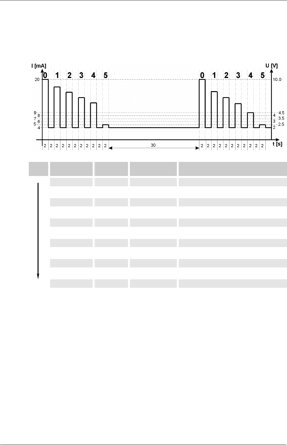
HDA.ISO – Analog signal ISO to HDA 5500
The HDA.ISO signal consists of 4 measured values (ISO 4 / ISO 6 / ISO 14 / ISO 21
/ Status) which are output sequentially. Synchronization with the downstream control
unit is a prerequisite.
The signal output is as follows:
Time Measured
variable
Signal duration
in s
Current/Voltage
Start signal 0 -- 2 20 mA / 10 V
Pause 2 4 mA / 2 V
Signal 1 > 4 µm 2 Current / Voltage for signal
Pause 2 4 mA / 2 V
Signal 2 > 6 µm 2 Current / Voltage for signal
Pause 2 4 mA / 2 V
Signal 3 > 14 µm 2 Current / Voltage for signal
Pause 2 4 mA / 2 V
Signal 4 > 21 µm 2 Current / Voltage for signal
Pause 2 4 mA / 2 V
Signal 5 Status 2 Current/voltage for signal
Pause 30 4 mA / 2 V