
Specifications


Table Of Contents
- Imprint
- Documentation Representative
- © HYDAC FILTER SYSTEMS GMBH
- Contents
- Preface
- Safety information
- Storing the CS
- Decoding the model code label
- Checking the scope of delivery
- CS1000 Features
- CS1000 Restrictions on use
- CS1x1x dimensions (without display)
- CS1x2x dimensions (with display)
- Hydraulic connection types
- Fastening / mounting the CS1000
- Display rotatable/Adjustable As Needed
- CS1000 hydraulic installation
- Electrical connection of the CS1000
- Setting the measuring mode
- Operating the CS1x2x using the keypad
- Overview of menu structure
- Using switching output
- Setting limit values
- Reading the analog output
- Status Messages
- Connecting CSI-D-5 (Condition Sensor Interface)
- Connecting the CS1000 to an RS-485 bus
- Communicating with the CS1000 via the RS-485 bus
- Taking the CS1000 out of operation
- Disposing of CS1000
- Spare Parts and Accessories
- Cleanliness classes - brief overview
- Checking/resetting default settings
- Technical data
- Recalibration
- Customer Service
- Model Code
- EC declaration of conformity
ContaminationSensor CS 1000 Electrical connection of the CS1000
HYDAC FILTER SYSTEMS GMBH
en(us)
Page 27/112
BeWa CS1000 3764916 300 en-us 2012-08-29.doc 2012-08-29
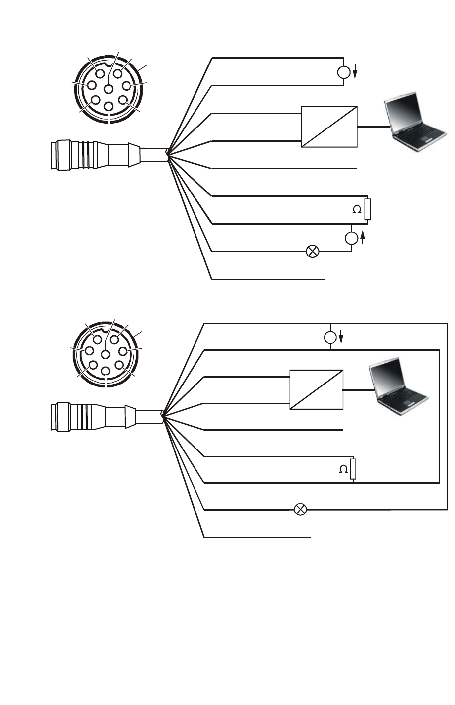
Connecting cable ends - Examples
HSI
RS-485 +
RS-485 -
250
1
2
3
4
5
6
7
8
Shield
24 V DC
5 V DC
SPS Eingang
PLC Input
SPS Entrée
white
green
pink
blue
grey
brown
yellow
red
USB
RS-485
Converter
=
=
1
7
6
5
4
3
2
Schirm
Shield
Blindage
8
Circuit diagram: with two separate power supplies. (e.g. 24 V DC and 5 V DC)
1
2
3
4
5
6
7
8
Shield
24 V DC
white
green
pink
RS-485 +
RS-485 -
blue
grey
brown
yellow
red
USB
RS-485
Converter
HSI
=
250
1
7
6
5
4
3
2
8
SPS Eingang
PLC Input
SPS Entrée
Schir
m
Shield
Blindage
Circuit diagram: with one power supply. (e.g. 24 V DC).
To prevent a ground loop, connect the shield of the connector cable if and only if the
CS1000 is not grounded or not sufficiently connected to the PE conductor.