
Specifications


Table Of Contents
- Imprint
- Documentation Representative
- © HYDAC FILTER SYSTEMS GMBH
- Contents
- Preface
- Safety information
- Storing the CS
- Decoding the model code label
- Checking the scope of delivery
- CS1000 Features
- CS1000 Restrictions on use
- CS1x1x dimensions (without display)
- CS1x2x dimensions (with display)
- Hydraulic connection types
- Fastening / mounting the CS1000
- Display rotatable/Adjustable As Needed
- CS1000 hydraulic installation
- Electrical connection of the CS1000
- Setting the measuring mode
- Operating the CS1x2x using the keypad
- Overview of menu structure
- Using switching output
- Setting limit values
- Reading the analog output
- Status Messages
- Connecting CSI-D-5 (Condition Sensor Interface)
- Connecting the CS1000 to an RS-485 bus
- Communicating with the CS1000 via the RS-485 bus
- Taking the CS1000 out of operation
- Disposing of CS1000
- Spare Parts and Accessories
- Cleanliness classes - brief overview
- Checking/resetting default settings
- Technical data
- Recalibration
- Customer Service
- Model Code
- EC declaration of conformity
ContaminationSensor CS 1000 Electrical connection of the CS1000
HYDAC FILTER SYSTEMS GMBH
en(us)
Page 26/112
BeWa CS1000 3764916 300 en-us 2012-08-29.doc 2012-08-29
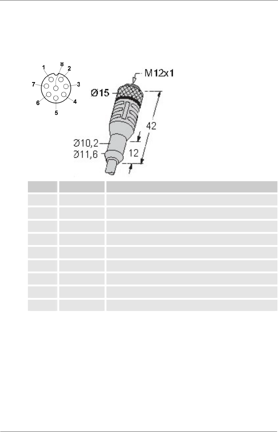
Connection cable - assignment / color coding
Our accessories list on page 95 includes the required connection cables of various
lengths with one connection plug (8-pole, M12x1, according to DIN VDE 0627) and
an open end.
HYDAC accessory cable color coding is listed in the table below.
Pin Colour Connection to
1 White Supply voltage 9 ... 36 V DC
2 brown Analog output + (active)
3 Green GND supply voltage
4 yellow GND ANALOG / SWITCH OUTPUTS
5 grey HSI (HYDAC Sensor Interface)
6 Pink RS485 +
7 blue RS485 -
8 Red Switching output (passive, n.c.)
Housing - screen