
Specifications


Table Of Contents
- Imprint
- Documentation Representative
- © HYDAC FILTER SYSTEMS GMBH
- Contents
- Preface
- Safety information
- Storing the CS
- Decoding the model code label
- Checking the scope of delivery
- CS1000 Features
- CS1000 Restrictions on use
- CS1x1x dimensions (without display)
- CS1x2x dimensions (with display)
- Hydraulic connection types
- Fastening / mounting the CS1000
- Display rotatable/Adjustable As Needed
- CS1000 hydraulic installation
- Electrical connection of the CS1000
- Setting the measuring mode
- Operating the CS1x2x using the keypad
- Overview of menu structure
- Using switching output
- Setting limit values
- Reading the analog output
- Status Messages
- Connecting CSI-D-5 (Condition Sensor Interface)
- Connecting the CS1000 to an RS-485 bus
- Communicating with the CS1000 via the RS-485 bus
- Taking the CS1000 out of operation
- Disposing of CS1000
- Spare Parts and Accessories
- Cleanliness classes - brief overview
- Checking/resetting default settings
- Technical data
- Recalibration
- Customer Service
- Model Code
- EC declaration of conformity
ContaminationSensor CS 1000 CS1000 hydraulic installation
HYDAC FILTER SYSTEMS GMBH
en(us)
Page 23/112
BeWa CS1000 3764916 300 en-us 2012-08-29.doc 2012-08-29
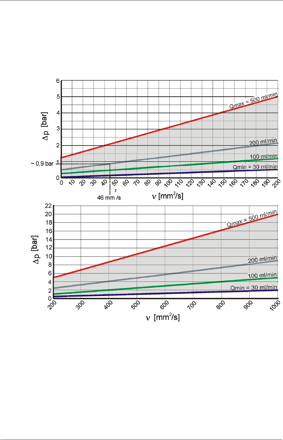
Flow rate, differential pressure
p
and viscosity
characteristics
Differential pressure
p
and viscosity
characteristics. All the values indicated in
the figures below apply regardless whether the direction of flow is A->B or B->A.
Note that the permissible measured volumetric flow is 30 … 500 ml/min.
If you are unable to achieve the required flow values, we offer an extensive line of
accessories with various conditioning modules.
For example:
You are using a fluid with a viscosity
of 46 mm²/s at a pressure difference
p
of
~0.9 bar, so that you achieve a flow rate of approx. 100 ml/min.
The flow rate depends on the viscosity of the medium and the differential pressure
p
via the sensor.