
Specifications


Table Of Contents
- Imprint
- Documentation Representative
- © HYDAC FILTER SYSTEMS GMBH
- Contents
- Preface
- Safety information
- Storing the CS
- Decoding the model code label
- Checking the scope of delivery
- CS1000 Features
- CS1000 Restrictions on use
- CS1x1x dimensions (without display)
- CS1x2x dimensions (with display)
- Hydraulic connection types
- Fastening / mounting the CS1000
- Display rotatable/Adjustable As Needed
- CS1000 hydraulic installation
- Electrical connection of the CS1000
- Setting the measuring mode
- Operating the CS1x2x using the keypad
- Overview of menu structure
- Using switching output
- Setting limit values
- Reading the analog output
- Status Messages
- Connecting CSI-D-5 (Condition Sensor Interface)
- Connecting the CS1000 to an RS-485 bus
- Communicating with the CS1000 via the RS-485 bus
- Taking the CS1000 out of operation
- Disposing of CS1000
- Spare Parts and Accessories
- Cleanliness classes - brief overview
- Checking/resetting default settings
- Technical data
- Recalibration
- Customer Service
- Model Code
- EC declaration of conformity
ContaminationSensor CS 1000 Hydraulic connection types
HYDAC FILTER SYSTEMS GMBH
en(us)
Page 18/112
BeWa CS1000 3764916 300 en-us 2012-08-29.doc 2012-08-29
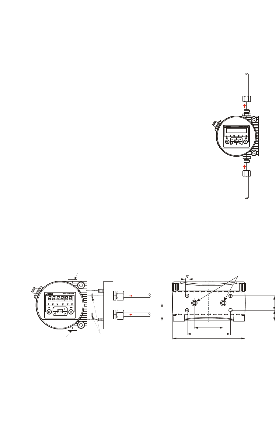
Hydraulic connection types
Install the CS in such a way that the flow runs from bottom to top. Use port A / C as
the INLET and B / D as the OUTLET.
Pipe or hose connection (type CS1xxx-x-x-x-x-0/-xxx)
Hydraulic connection is done via ports A and B. Connection
thread G1/4 according to ISO 228.
Make sure that the flow runs through the sensor from
bottom (A) to top (B).
A
B
Flange connection type (Type CS1xxx-x-x-x-x-1/-xxx)
Hydraulic connection is done via ports C and D. Two O-rings are used to form a seal
between the CS and a flange, connecting plate or manifold mount. Four M6 threads
are prepared for fixing the CS1000. Ports A and B are sealed off with screw plugs
[1]. Sealing with the manifold block or mounting plate is done via two O-rings [2]
(4.48 x 1.78 FPM, see Chapter "Spare Parts + Accessories").
[1] [2]
[1]
C
A
B
D
CD
25
15 20
100
40
60
12/16
4xM6
[2]
View from below.
All dimensions in mm.