Connect™ Monitor Manual Document No: WT 9437 Issue Date: August 2020 ® is a registered Trade Mark of Wellington Drive Technologies ©2020 Wellington Drive Technologies Limited 21 Arrenway Dr, Albany, North Shore 0632, New Zealand PO Box 302-533, North Harbour, North Shore 0751, New Zealand P: +64 9 477 0415 Fax: +64 9 414 6591 E: info@wdtl.com www.wdtl.
Connect™ Monitor Instructions Manual AUGUST 2020 Warnings Please read the following warnings to maintain the safe operation and continued performance of your Wellington Drive Technologies Limited Connect Monitor: Warnings Important Do's and Don'ts Installation Installation of the Connect Monitor otherwise than in accordance with the “Description & Install” section of this manual will invalidate the warranty. The Connect Monitor must only be installed and configured by trained and authorized staff.
Connect™ Monitor Instructions Manual AUGUST 2020 Correct disposal The Connect Monitor is subject to EU Directive 2012/19/EU (WEEE) for ewaste. It may also be subject to other national legislation for the safe disposal of e-waste. The Connect Monitor must not be disposed of in municipal collections; it must be disposed of through an approved WEEE collection point. Alternatively, Connect Monitor may be returned to an authorized Wellington Drive Technologies Limited distributor at the end of its working life.
Connect™ Monitor Instructions Manual AUGUST 2020 Introduction The Connect Monitor by Wellington is a battery operated selfcontained Bluetooth LE transmission sensor hub designed for providing radio connectivity to existing refrigeration equipment in the market. It adds functionality such as telemetry connectivity, asset tracking, and proximity based marketing.
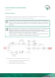
Connect™ Monitor Instructions Manual AUGUST 2020 Process Overview The following process details the steps required for Connect Monitor installation, commissioning, and activation within the Wellington Connect ecosystem and reporting tools. An NFC phone is required to activate Bluetooth connectivity. These steps are marked with the NFC symbol in the process diagram.
Connect™ Monitor Instructions Manual AUGUST 2020 The Connect Monitor arrives from manufacturer with Bluetooth communications configured to OFF to preserve battery and extend usable life. The Manufacturer, Owner, and Brand IDs are factory set to BLANK. Activation of the Connect Monitor turns on Bluetooth communications and must be performed using an NFC capable device. All other configurations can be performed over Bluetooth connection.
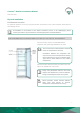
Connect™ Monitor Instructions Manual AUGUST 2020 Physical Installation Position and Location For optimum operation, the choice of physical location and position of the Connect Monitor should meet all the following criteria. If installation in accordance to the below conditions proves to be challenging, please contact your WDTL representative to review appropriate recommendations.
Connect™ Monitor Instructions Manual AUGUST 2020 FOR COOLERS WITH EVAPORATORS LOCATED AT THE BOTTOM OF THE CABINET: Connect Monitor must be mounted in front of the evaporator inlet. This ensures the Connect Monitor reads the return air temperature correctly. Installation not in the airflow stream may result in incorrect temperature reading due to placement in an air circulation deadspace that is often different to the overall cabinet temperature.
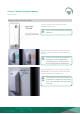
Connect™ Monitor Instructions Manual AUGUST 2020 FOR ALL INSTALLATION TYPES: The side closer to the screw holes must be installed facing the door. This is critical to ensure door opening detection. When installed, the barcode should be facing the back of the cooler, and hence not be visible from the front. If you can see the barcode label after installation, Connect MONITOR is installed facing the wrong way and door openings will not be detected.
Connect™ Monitor Instructions Manual AUGUST 2020 Procedure STEP 1 Clean mounting surface using the supplied alcohol wipe. STEP 2 Wait for surface to dry before attaching Connect Monitor. If cabinet is cold, ensure there is no condensation on the surface prior to attaching the device. STEP 3 Expose adhesive on the back of the device by removing liner. STEP 4 Firmly press Connect Monitor onto mounting surface and hold for at least 5 seconds.
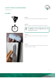
Connect™ Monitor Instructions Manual AUGUST 2020 STEP 5 (optional) Insert the two #8 self-drilling screws provided into the mounting holes. Use a standard Phillips head driver to secure screws into the mounting surface (screws will pierce foam tape and seal).
Connect™ Monitor Instructions Manual AUGUST 2020 Connect Monitor Activation via NFC Prerequisites • An NFC capable mobile phone is required to perform Activation on an Connect Monitor. o Prior to initiating the process, check that the mobile phone has NFC enabled. Please refer to the phone user manual for instructions on how to enable NFC. • Make sure you have the latest version of SCS Connect Field application installed and activated to the correct database.
Connect™ Monitor Instructions Manual AUGUST 2020 2. The following message will be visible: “Move your mobile device close to the SCS Monitor you wish to connect to”. 3. Place your mobile phone on top of the Connect Monitor, as depicted, until “CONNECTING MoXXXXXXXX” message is displayed. You may need to hold the phone over the Connect Monitor for a few seconds to establish an NFC connection.
Connect™ Monitor Instructions Manual AUGUST 2020 4. “CONNECTING MoXXXXXXXX“ will be displayed when NFC is enabled. The phone may emit a sound and vibration when NFC is successfully enabled on the Connect Monitor. You will be automatically connected to Connect Monitor via Bluetooth for visualization and set up. 5. Upon successful connection you will be prompted with the configuration screen. Please specify the Manufacturer, Owner and Brand.
Connect™ Monitor Instructions Manual AUGUST 2020 Please refer to Field App Quick Steps for detailed instructions on how to: • WT9403_Set IDs through SCS Connect Field App • WT9404_Set Asset Details through SCS Connect Field App Available on request. Bulk Activation process through SCS Field Open the SCS Field app and follow the steps below. This option is only available for users with the appropriate permissions.
Connect™ Monitor Instructions Manual AUGUST 2020 2. “Ready to Scan” screen will be displayed. From this screen, select START BULK ACTIVATION. 3. “Move your mobile device close to the SCS Monitor you wish to activate” message will be visible.
Connect™ Monitor Instructions Manual AUGUST 2020 4. Place your mobile phone on top of the Connect Monitor, as depicted, until “CONNECTING MoXXXXXXXX“ message is displayed. You may need to hold the phone over the Connect Monitor for a few seconds to establish an NFC connection. If this process takes longer than 5 seconds, try slowly hovering your phone over the device to facilitate alignment of the device NFC module and the phone NFC antenna. 5.
Connect™ Monitor Instructions Manual AUGUST 2020 7. When all Connect Monitor have been activated, please select STOP BULK ACTIVATION It is vital to configure the device to the correct Manufacturer and Owner. -This feature is NOT supported for Bulk Activation in the Field Trial Prototype units. So manufacturer and owner needs to be set up at the point of installation- This ensures only authorized connections can be made to the device, and data collection is only possible by the assigned Owner.
Connect™ Monitor Instructions Manual AUGUST 2020 Connecting to Connect Monitor Connecting to Connect Monitor requires the SCS Field app, available on Google Play Store and the App Store. Make sure you have the latest version of SCS Field application installed and activated to the correct database. Check for updates in the App Store or Google Play. Detailed instructions on how to install and activate Field app can be found in Field App Quick Steps, available on request.
Connect™ Monitor Instructions Manual AUGUST 2020 NFC 1. Select NFC from the bottom banner. 2. Hold the phone close to the Connect Monitor you wish to connect to. You may need to hold the phone over the Connect Monitor for a few seconds to establish an NFC connection. If this process takes longer than 5 seconds, try slowly hovering your phone over the device to facilitate alignment of the device NFC module and the phone NFC antenna.
Connect™ Monitor Instructions Manual AUGUST 2020 3. The phone will read the NFC tag inside the Connect Monitor and connect to the device over Bluetooth.
Connect™ Monitor Instructions Manual AUGUST 2020 QR CODE 1. Select BARCODE from the bottom banner 2. Point the camera at the QR code included in the Connect Monitor label. FOR FIELD TRIAL UNITS ONLY!! If the device is already installed, the label will be facing the FRONT of the cooler.
Connect™ Monitor Instructions Manual AUGUST 2020 3. The phone will read the QR code and connect to the Connect Monitor over Bluetooth.
Connect™ Monitor Instructions Manual AUGUST 2020 Parameters All parameters are set to read and write by any level of user unless otherwise stated. HIGH TEMPERATURE ALARM SET POINT (not supported in Field Trial Prototype units) Description The Absolute Temperature above which an alarm is triggered. The measured temperature must exceed this setpoint for a time specified by Temperature Out-Of-Spec Alarm Delay before the alarm is triggered. Parameter Range -40.0 to 15.0 or disabled Increment & Units 0.
Connect™ Monitor Instructions Manual AUGUST 2020 TEMPERATURE CALIBRATION OFFSET (not supported in Field Trial Prototype units) Description Parameter Range The offset amount applied to the Air Temperature parameter to compensate between the measured value and the actual Air-Temperature inside the cabinet used by the equipment control system. -10.0 to 10.0 °C Increment & Units Default 0.1 °C 0.0 °C This parameter is intended to be set automatically by the Field app upon selection of equipment model.
Connect™ Monitor Instructions Manual AUGUST 2020 Connect Monitor LED Indicator Connect Monitor is equipped with a single LED indicator, used to impart meaningful messages through flashing sequences. The operating scheme is as follows: Connect Monitor State Pattern Purpose Activation successful Three 5ms flashes at 200 ms intervals Demonstrates a successful activation, removed from flight mode, and advertising Bluetooth. Supports recognition of firmware startup and reboot.
Connect™ Monitor Instructions Manual AUGUST 2020 Technical Specs Technical Specification Table POWER Battery Life* ENVIRONMENTAL Operational Temperature Range Storage Temperature Range 5+yrs -35°C to +40°C (-31°F to +104°F) <90% RH non-condensing -40°C to +85°C (-40°F to +185°F) <90% RH non-condensing CONNECTIVITY Bluetooth™ Capability Bluetooth™ SMART NFC Capability Passive read/write Supported Windows O/S for GUI module Windows 7 Windows 8 Windows 8.
Connect™ Monitor Instructions Manual AUGUST 2020 Compliance** (includes EMC, RF, Safety&Health) CE RED Certification: • EN300328 V2.2.2, EN300330 V2.1.1, EN3014891&17 & -3, EN62479, EN62368-1, EN60529.
Connect™ Monitor Instructions Manual AUGUST 2020 FCC Statement: This equipment has been tested and found to comply with the limits for a Class B digital device, pursuant to part 15 of the FCC Rules. These limits are designed to provide reasonable protection against harmful interference in a residential installation. This equipment generates, uses and can radiate radio frequency energy and, if not installed and used in accordance with the instructions, may cause harmful interference to radio communications.
Connect™ Monitor Instructions Manual AUGUST 2020 Glossary Term Used Definition CE Mark Conformité Européenne. The CE mark signifies that the product conforms to all applicable European Directives required by the European Economic Area (EEA). Cooler Unit The unit containing the refrigeration system and an insulated space for storing and displaying product. cUL Mark The cUL Mark signifies that the product conforms to the relevant safety compliance required by the USA and Canada.
Connect™ Monitor Instructions Manual AUGUST 2020 Products Products are the items being stored inside the refrigerated cabinet, for example chilled drinks. Refrigeration System The components comprising the complete refrigeration circuit, including controller, evaporator, expansion valve, condenser, compressor and evaporator fan. Sensor Sensors are devices which generate a signal used to control devices as a result of a detected environmental change.