
User Manual


7
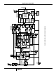
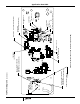
Receiver Noise/Gain Analysis
The ISL36342U is implemented on FR-4 material. It uses 50Ω
coplanar micro-strip traces which have a loss of 0.35dB/in at
2.442GHz. These losses are small, but should be considered
when calculating the overall noise figure. The ISL36342U uses
two diversity antennas. The first component is the antenna
diversity select switch. This has an insertion loss of 1dB. The
input trace to the switch along with the matching network
associated with the switch brings the insertion loss to 2dB. The
next component is a low pass filter. This filter provides transmit
harmonic suppression. Its insertion loss is 1dB including the
trace loss and matching loss from T/R switch. The next
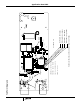
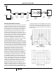
component is a bandpass filter. This filter limits the front end
pass band to the ISM band, and provides out-of-band rejection
for all undesired signals (e.g., cell phones). The filter
characteristic is shown is Figure X. The insertion loss from this
filter is 2.5dB including the effect of trace length. The bandpass
filter is followed by a Transmit/Receive (T/R) switch. This switch
connects the LNA or the Power Amplifier (PA) to the antennas.
The insertion loss from this switch is 2.5dB including the effects
of trace lengths and matching components. The LNA is the next
component in the receive path. The LNA is inside the
HFA3683A RF/IF converter and synthesizer, which also
contains a image reject mixer, as well as the frequency
synthesizer for the first Local Oscillator (LO). The first LO is low
side injected to mix the desired channel to the Intermediate
Frequency (IF) of 374MHz. The first LO tunes in 5MHz steps
and is 374MHz below the ISM band channels. The first LO tune
from 2038MHz to 2110MHz. The cascaded noise figure and
gain of the LNA and the image reject mixer in the high gain
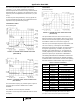
mode is 3.7dB and 25dB respectively. The IF filter is a Surface
Acoustic Wave (SAW) filter. The passband of the SAW filter is
±10MHz which provides adjacent channel rejection. It has
linear phase, sharp attenuation characteristics and provides
50dB of ultimate suppression. The final component is the
HFA3783 I/Q modulator/demodulator and synthesizer. The
HFA3783 contains AGG amplifiers and a quadrature baseband
converter. The HFA3783’s maximum gain is 61dB while the
worst case noise figure is 8dB. The HFA3783 provides complex
I and Q filtered inputs to the base-band processor. A spread
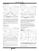
sheet showing the noise gain analysis is shown in Figure X. In
the low gain, mode the LNA gain is switched via the AGC to
-9dB of loss. The noise gain cascade for the low gain mode is
shown in Figure X.
HFA 3683A
HFA 3783
Bandpass Filter
USN 30172450
2dB IL
T/R Switch
UPG-152TA
1dB IL
OCP 27
OIP3 50
Diversity
Switch
UPG-152TA
1dB IL
OCP 27
OIP3 50
Lowpass Filter
LTF3216L
1dB IL
LNA/Image
Rejection Mixer
Gain 25 dB
NF 3.7dB
OCP -7.5
OIP3 12
374MHz
Saw Filter
8.5dB IL
HFA 3783
Gain 61
NF 7dB
OCP -14.3
OIP3 1.5
FIGURE 4.
FIGURE 5. INPUT FILTER
FIGURE 6. SAW FILTER
Application Note 9949