
Specifications


Table Of Contents
54
- Equipping a Conergy WR with a datalogger card
(Illustration: Conergy WR 2)
- Equipping all Conergy WRs with a COM Card
The data recorder has two RS-232 interfaces for the connection with
personal computer and modem.
Example
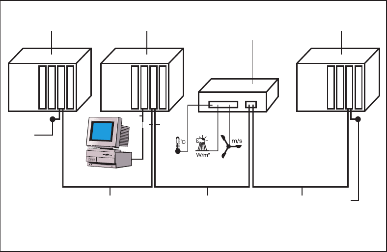
Example: Recording and archiving inverter and sensor data by means of a
datalogger card and sensor box.
The cards communicate within the Conergy WR unit via its internal net-
work. External communication (LocalNet) is effected via the COM cards.
Each COM card has two RS-485 interfaces for entry and exit. Connection
is effected with RJ45 plugs.
The first Conergy WR unit with COM card can be located at a distance of
up to 1000 m from the last Conergy WR unit with COM card.
LocalNet automatically identifies different system upgrades (data recor-
der, sensor card, ...)
To differentiate between several identical system upgradings, the respec-
tive units must have an individual number.
To define each Conergy WR clearly in the LocalNet, an individual number
must also be allocated to each Conergy WR.
For the respective procedure, please consult the chapter „Setup Menu“ in
your operating instructions.
Configuration
COM Card
(5)(6)
Sensor Box in
external Housing
OUT
IN
ENS
Conergy WR 3
Datalogger C.
PC
(5)
(6)(6)
COM Card
COM Card
(5) Blind plug
(6) Data cable
IN OUT
IN OUT
PC
IN
OUT
ENS
ENS
RS-232
Conergy WR 1 Conergy WR 2