
Specifications


Table Of Contents
47
Depending on the options installed in your Conergy WR unit, you have
the following alternatives to connect the solar inverter at the DC solar
modules and to the public AC mains:
Note! Only cables up to a cross section of 4 mm² are permitted for
the AC-plug-type connector.
Only use cables with a cross-section of 4 sq.mm for the Conergy WR
5900.
Important! We recommend AC protection as follows:
- A special16 A fuse for each Conergy WR 1700 and 3300
- A special 25 A fuse for each Conergy WR 4600 and 5900
- Alternatively for Conergy WR 4600 and 5900: 32 A , type „C“ miniature
circuit-breaker
1. Terminal block (connection within the housing)
2. DC plug (choice of up to 5 DC sockets, AC connection within the hou-
sing)
3. DC plug and AC plug connection (choice of up to 5 DC plug pairs, AC
plug connection)
The following chapters show the connection of the Conergy WR unit
separately for each one of the connection alternatives.
Connection
alternatives
- Fix the Conergy WR unit to the wall as shown in chapter „Installation“.
The housing is designed for a cable channel of up to 50 mm height which
can be located directly below the connection area, without
- cables visible below the Conergy WR unit
- impairing access to the connection area and the slot- in board area
Permissible cross-sections for AC and DC connection cables:
- cable without wire end ferrules: 6 mm² and 10 mm²
- cable with wire end ferrules: 6 mm²
Note! Tighten the screws of the terminal strip with 1.8 Nm.
1. Terminal
block
- feed the 3 pole connection cable
to the public mains through the
connector rail and strain relief
device and slide it into the termi-
nal block
- connect the leads of the connec-
tion cable as marked on terminal
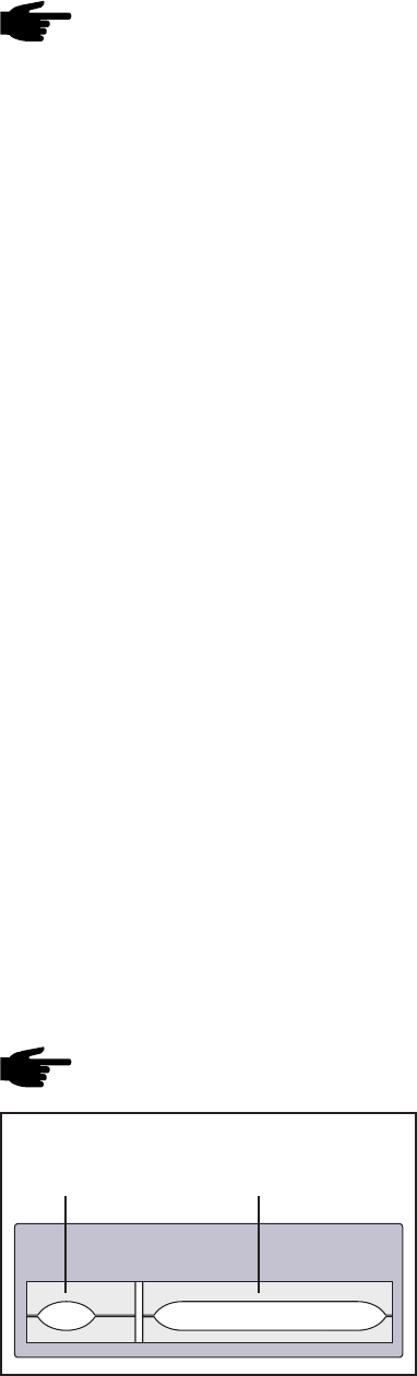
connection rail for alternative with terminal rail
Strain relief for the
connection cables (DC)
strain relief for
connection cable (AC)