
Specifications


Table Of Contents
43
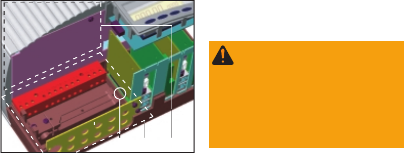
(3) connection section is open
(4) power stage
Warning! Hazard due to
supply voltage and DC-volta-
ge from the solar modules.
Only trained service staff are
authorized to open the sepa-
rately insulation-enclosed
power stage
(3) (4)
(5)
- loosen securing screw (5) and remove wall mounting frame
Conergy WR
(continued)
The Conergy WR unit can only be installed inside buildings or on outside
locations provided that they are protected from rain or snow.
- During certain operation phases the Conergy WR unit may develop a
slight noise level, for this reason it should not be installed in the immedi-
ate vicinity of living areas
- the Conergy WR unit is not to be set up in areas where there is heavy
dust development
- the Conergy WR unit is not to be set up in areas where there is heavy
incidence of conducting dust particles (for example iron filings)
Choosing the
location
Installation
Make the best possible use of your Conergy WR unit by additionally
observing the following conditions:
- mains impedance should not be unnecessarily increased by a too nar-
row AC conductor cable cross section between the Conergy WR unit
and the in-house distribution panel. The AC conductor cable resistance
between the Conergy WR unit and the house distribution panel must
not exceed 0,5 Ohm.
- install it only on a solid vertical wall
- The ambient temperature should not be under minus 20 degrees or
over 50 degrees centigrade.
- No objects must be located within a distance of 15 cm around the air
vents on both sides of the Conergy WR unit
- Keep a lateral distance of 20 cm between individual Conergy WR units.
- The air flow direction within the inverter is from left to right (cold air
intake left, hot air exit right).
- When installing the Conergy WR unit in a switch panel cabinet (or
similar closed sections) it is necessary to make sure that the hot air
which develops will be discharged by forced ventilation.
Choosing the
location gene-
ral