
Installation manual


ENGLISH
Conergy AS
Owners Manual
20
6 Connections at the Storage Tank
6.3 Connections for closed circuit systems
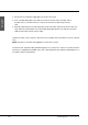
6.3.1 Installing the HEM-25-B module:
1. Fit the brass unions (P/No 60-1029) to the
sockets on the storage tank.
2. Attach the brass union (P/No 60-1033) to the
top connection of the heat exchanger.
3. Insert the bottom connection of the heat
exchanger to the bottom brass union on the
storage tank.
4. Hook the Mounting Bracket (P/No 20-3085) to
the slot on the rear of the HEM-25-B case.
5. Using a suitable levelling device, ensure the
HEM-25-B module is vertical. Once in position,
screw fix the Mounting Clamp to the storage
tanks using the self drilling screws supplied.
6. Take the Hot Thermosiphon Pipe (P/No 60-
1048), and check the length to ascertain if it needs to be shortened. This will be the case on
250L and 400L installations. Trim the copper to suit.
7. Insert the copper tube to the brass unions and tighten. Even out the insulation on the Hot
Thermosiphon Pipe to cover as much of the brass unions and exposed copper tube as
possible.
8. Using a suitable thread sealant, fix the Cold Inlet Tee (P/No 60-1116) into the inlet socket of the
storage vessel. This assembly is used to provide an inlet for potable water into the storage
vessel, and a thermowell for measuring the temperature of the water in the storage vessel. The
cold temperature sensor from the Pump Module is inserted into this thermowell.
60-1029
60-1048
60-1033
20-3085
60-1116
Spirit Level
(not included)
60-1029