Owner & Installation Manual Conergy Active System Open and Closed Split Systems www.conergy.com.
Table of Contents ENGLISH 1 3 1.1 The environmental benefits 3 1.2 Why Conergy? 3 1.3 What is a Split System? 3 1.4 System components 5 1.5 Your Conergy AS model number 7 1.6 System operation 7 1.7 Important safety information 8 1.8 What should I do during holidays? 8 Troubleshooting 9 What should I check before making a service call? 9 2 2.1 3 System Maintenance 11 3.1 Pressure limiting valve 11 3.2 Draining the storage tank 11 Important Installation Notes 13 4.
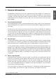
1 Owners Information Owners Information Congratulations on buying one of the most advanced solar hot water heaters in the world. As the owner of a Conergy solar water heater you may have some questions about the system and how it operates. Your solar water heater model is commonly referred to as an Active, Split or Ground Mounted open circuit or closed circuit system and is one of the most efficient solar water heater types available. 1.
1 Owners Information ENGLISH 1.3.1 What is an open circuit system? An Open Circuit System is one where the water used in the household circulates through the solar collector panels. The circulating pump draws colder water from the lower section of the container and circulates this water through the collectors before returning it to the container at a point higher than the point of draw-off thus transferring solar energy to the storage tank.
1 Owners Information System components The main components of your solar water heater are the household water storage tank, the solar collector(s), circulation pump module & controller, heat exchange module (closed circuit models only) and the Ancillary Energy Support (AES) System. 1.4.1 Storage tank & solar collectors Open circuit tank, closed circuit tank, solar collectors The Conergy water storage tank is used to store the heated water ready for household use.
1 Owners Information ENGLISH water temperature falls below 60°C and will only consume electricity until the water temperature is increased to 60°C then turns off again. For gas AES systems a continuous flow gas water heater is fitted adjacent the storage tank in series with the hot water supply from the storage tank and the household hot water pipe work system. As the hot water from the solar storage tank passes through the gas heater its temperature is automatically monitored by the gas heater.
collector temperature rises above 190°C, the circulation pump will be initiated to reduce the collector temperature to below 185°C. This is to protect the collector from prolonged periods of extreme temperature. 5. 1.5 System Cooling. During the collector circuit temperature control operation, if the storage tank water temperature has risen above the set 70°C maximum, the controller will initiate the pump to reduce the excess tank temperature back to the set point of 70°C.
1 Owners Information 1.7 Important safety information ENGLISH 1. 2. 3. All water heaters have the ability to produce hot water very quickly. To reduce the risk of scald injury, it is recommended that a temperature control valve be fitted to the hot water supply pipe work. This valve should be checked at regular intervals to ensure its operation and settings remain correct.
2 Troubleshooting Troubleshooting It is important to know that there are no user serviceable components in the system, and as such, it is recommended that no covers be removed and no adjustments made to the system settings by anyone other than an authorised Conergy representative. 2.1 What should I check before making a service call? If there is not enough hot water, it is recommended that the following points are considered before making a service call.
ENGLISH 2 Troubleshooting 2.1.5 10 Water discharge from frost valve If your system has a frost valve fitted it will be located at the bottom corner of the collector. In temperatures that cause frost or freezing the valve will open and some water will discharge from this valve. There is nothing that needs to be done to the valve or the system, it is operating correctly. The water will stop discharging once the valve has warmed enough to close again, usually as the frost clears.
3 System Maintenance System Maintenance The Conergy system is designed so that there is little to do regarding system maintenance. Personally inspecting or servicing the system is not recommended. Should you decide to personally inspect the roof mounted solar collectors it is essential that you use all safety devices required to ensure your safety. Glass cleaning usually occurs by natural rainfall.
4. Disconnect the cold water supply pipe connection to the tank. ENGLISH 5. Fit a ½” flexible drain pipe to the cold connection on the tank. Place the open end of the drain hose in a location where it is safe for the hot water to drain away from the tank. 6. Manually open the pressure and temperature relief valve which will allow air into the tank. The water within the tank will flow out via the flexible drain pipe fitted to the cold inlet connection. Hold the valve open until the tank is empty.
4 Important Installation Notes Important Installation Notes Do not commence an installation until you have satisfied yourself that all safety issues associated with working on and lifting components onto a roof have been addressed. All work associated with the installation must comply with local authority regulations including AS/NZS 3500.4.2, where these installation instructions and local regulations are in conflict, local regulations must prevail. 4.
5 Collector Installation ENGLISH 5 Collector Installation After selecting the solar collector location, the final check before installation is that the available roof space is sufficient for the solar collectors being installed. System Roof space width required 1 panel 2000 mm 2 panel 3000 mm 3 panel 4000 mm 1 panel = 2000 mm 2 panels = 3000 mm 3 panels = 4000 mm 500 3000 mm 500 500 500 The length up the roof must be at least 3 metres for all installations.
4. Adjust the mounting rail so that it is 15 – 20 mm higher (up the roof) on the right side, then screw fix the collector straps to the roof trusses using the pre-punched holes. 5. Take the first solar collector and place it on the collector mounting rail, at the leftmost end. For a single collector installation, go directly to step 8. 6. Loosely fit the two collector connectors (Detail B, 60-1002) to the two copper tube spigots on the right side of collector. 7.
5 Collector Installation ENGLISH 15. Assemble and install the Hot Connection Union assembly (Detail A) as follows: a. Take the temperature well (Detail A – 60-1072) and slide it onto the copper spigot at the top right of the collector array. Tighten the assembly taking care not to twist the copper tubes of the collector. Make sure you use correctly sized spanners and that the nut is held steady whilst the compressing plug is tightened. b.
5 Collector Installation ENGLISH 60-1003 60-3028 60-3047 60-4011 Detail D Detail E 60-3029 Detail F Conergy AS Detail G Owners Manual 17
6 Connections at the Storage Tank ENGLISH 6 Connections at the Storage Tank The Storage Tank is installed and connected to the plumbing installation as normal and detailed in the Conergy installation instructions supplied with the water heater. The household plumbing connections should be made to the tank socket fittings on the left side of the storage tank. This leaves the right side fittings free for connection to the solar collector system.
6.2 ENGLISH 6 Connections at the Storage Tank Connections for open circuit systems with a PM-600 1. Ensure that the pump module is installed in an accessible position. 2. Apply thread tape or a suitable sealant to the thread of the ¾” BSP to ½” compression union (P/No 60-1029). Screw the union into the top outlet) socket on the right side of the storage tank. Fasten the Collector Hot Connection (Section 8.0, Step 2) into the compression union. 60-1032 3.
6 Connections at the Storage Tank 6.3 Connections for closed circuit systems ENGLISH 6.3.1 Installing the HEM-25-B module: 1. Fit the brass unions (P/No 60-1029) to the sockets on the storage tank. 2. Attach the brass union (P/No 60-1033) to the top connection of the heat exchanger. 60-1029 3. Insert the bottom connection of the heat exchanger to the bottom brass union on the storage tank. 60-1033 4. Hook the Mounting Bracket (P/No 20-3085) to the slot on the rear of the HEM-25-B case. 5.
6 Connections at the Storage Tank 1. Ensure that the pump module is installed in an accessible position. 2. Fit the brass nipples (P/No 60-5066) to both the connection ports on the HEM-25-B module. 3. Take one Fill Fitting (P/No 60-5157), and using a suitable thread sealant, fasten to the outlet side of the pump on the pump module. Remove the check valve in this port on PM-600 modules. 60-5157 60-1032 60-5157 60-1115 60-5066 60-5066 4.
6 Connections at the Storage Tank 6.3.4 Fill procedure for closed circuit systems: ENGLISH 1. The charging procedure is made in two stages. The first to leak test the system, using potable water. The second is to charge the system with ST-5 Solar Transfer Fluid. It is essential that the solar panels are not exposed to direct sunlight during this procedure. Cover if necessary. Fill Port Isolating Ball Valve 2.
7 Electrical Connections to the System Electrical Connections to the System ENGLISH 7 Note: 1. All electrical work must comply with local regulations and AS3000. 2. All electrical work must be conducted by a suitability licensed electrician. 3. Refer to the Owner’s Manual supplied with the tank for more detailed information on the specific requirements of the storage tank. 4. Do not turn on power to the system until it is filled with water. 5.
7 Electrical Connections to the System 7.2 Electrical connection for gas AES systems ENGLISH For models using a Gas AES module, it is required to install an external GPO adjacent the modules location. The module needs a 220-240 Volt, 50 Hz power supply that must be continuously available. The module is rated at 0.47 Amperes. Gas booster sample 7.3 Electrical installations for a PM-600 1. From the household electrical circuit, run a permanent 230 to 250 Volt A.C.
After conducting a final inspection of the electrical installation, the power may be turned on. Once the power is turned on, check the LCD screen of the solar controller within the Pump Module. Fifteen seconds after the power is applied the screen should read the sensor temperatures. If the temperatures are present, this indicates that the sensor cables are installed and connected correctly.
7 Electrical Connections to the System 7.3.1 Controller field settings for the Deltasol B solar controller ENGLISH It is not recommended that you alter the optimal factory settings or run the system in manual for extended periods. Changes in settings may adversely affect solar performance. Use Buttons 1 & 2 to scroll through the values. The fields should match the values in the table below.
8 Commissioning & Customer Hand Over When all connections have been completed the solar water heater can be filled with water. | Before turning on the cold water supply open one hot tap within the household to release air from the system during the filling process. Do not leave the open tap unattended during the filling process. | Turn on the cold water supply and wait for the system to fill. | When water flows from the open hot tap without air bursts then the hot tap can be closed.
9 Warranty ENGLISH 9 Warranty The Conergy Solar hot water system that you have purchased comes with a comprehensive 5 year parts and labour warrantly. The terms of the Warranty and Guarantee are set out below. 1. Your solar hot water system and its components are covered by a 5 year warranty against defective factory parts or workmanship from the date your hot water unit or solar collector is installed.
9 Warranty 7. Freeze damage to open circuit systems when installed in frost affected areas. The warranty only applies to the hot water unit and solar collector or components in the hot water unit and solar collector and does not cover any plumbing or associated parts, including but not limited to; pressure limiting valves, stop cocks, non return valves, electrical switches, pumps or fuses, supplied by any person installing the hot water unit or solar collector. 8.
55-4009-REV1-0910 For further information call your local Conergy service agent on 1300 137 602 (Australia only), or get in touch with your Conergy state office: NSW, ACT (Head Office) VIC, SA, TAS QLD, NT WA Phone 1300 724 531 Email sales@conergy.com.au Phone 1300 724 531 Email vic@conergy.com.au Phone 1300 724 531 Email qld@conergy.com.au Phone 1300 724 531 Email wa@conergy.com.