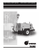
USER'S GUIDE & SAFETY MANUAL USER'S GUIDE & SAFETY MANUAL WDR505 Underground Pulling Trailer
Important Safety Notice Read and understand all procedures and safety instructions before using a Condux Underground Pulling Trailers. Observe all safety information on this page and note specific safety requirements as explained by procedures in this manual. Failure to follow these instructions could result in serious personal injury or death. ADVERTENCIA: Favor de leer y comprender todas las instucciones de operación y seguridad antes de usar la máquina. Si Ud.
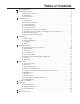
Table of Contents 1 General Information. . . . . . . . . . . . . . . . . . . . . . . . . . . . . . . . . . . . . . . . . . . . . . . . . . . . . . . . . . . . 4 2 Technical Specifications . . . . . . . . . . . . . . . . . . . . . . . . . . . . . . . . . . . . . . . . . . . . . . . . . . . . . . . . 6 3 4 5 6 7 8 9 10 A. Operational Conditions. . . . . . . . . . . . . . . . . . . . . . . . . . . . . . . . . . . . . . . . . . . . . . . . . . 6 B. Hydraulic Oil. . . . . . . . . . . . . . . . . . . . . .
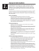
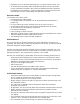
1. General Information PRODUCT DESCRIPTION The WDR505 pulling trailer provides up to 11,240 lbs. of pulling force and a max speed of 219 ft/min. It comes equipped with a digital meter counter, hydraulic dynamometer with set point and automatic control of the maximum pull, a noise reduction kit, as well as 2,600 feet of anti-twist rope a key feature. Anti-twist rope offers high flexibility, complete stability to rotation and increased efficiency during pulling operation.
• Operators must use personal protective gear (i.e. gloves, boots, helmet, etc.). • All maintenance operations, both scheduled and repair, must be carried out per the instructions included in this manual or following technical instructions provided by the manufacturer. Failure to follow these instructions relieves the manufacturer from any responsibility and voids their warranty.
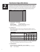
4. 2. Technical Specifications The Condux WDR505 Hydraulic Underground Pulling Trailer provides up to 9,000 lbs of continuous pulling force. Designed for installing underground cable, the WDR-505 is completely self-contained and transports easily from jobsite to jobsite. Industry leading features like antiwist rope and modular extension arms make the WDR-505 the most advanced puller in the market today.
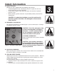
Safety Information A. SAFETY DEVICES Machine has been equipped with the following safety devices: • A load-limiting device that automatically stops the engine once the max. pre-set load value has been exceeded • A mechanical negative safety brake that stops all movement if hydraulic pressure is lost • Where possible, guards and covers are provided to protect personnel from moving parts 3. 3.
F. Rotating component pinch-point hazards Due to the nature of the work being performed and important system functionality, it is not possible to fully guard all rotating components. To minimize risks operators must: • Avoid any contact with the machine’s rotating components • Follow the anchoring instructions described in this manual • Follow all recommendations in this manual regarding the use of personal safety equipment G.
Transporting A. MACHINE LIFTING For machine lifting use only devices (overhead traveling cranes, lift trucks, ropes, cables, hooks, etc.) with a capacity equal to the weight to be lifted. Personel should not be on the machine when it is lifted. !DANGER: Failure to follow the recommendations in this section may create a dangerous situation and/or damage to the machine. The manufacturer’s warranty may also become void as a result. 3. 4. B.
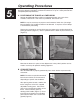
5. 5. Operating Procedures It is essential that the Underground Pulling Trailer be properly set up before operation. Using the following procedure will allow the unit to be set up in a short period of time and yield optimum performance. A. POSITIONING THE TRAILER & LOWER BOOM Position the WDR 505 Puller within an approximate boom arm reach of the manhole or duct bank. After trailer is positioned, lower boom arm.
Figure 5. Boom Arm Level to the Ground C. START PULLER Open control panel on side of WDR 505 and secure. Start the engine by holding the glow plug rocker switch unit the glow plug indicator light goes out (Figure 6). Turn the ignition key while holding the glow plug rocker switch until the OK light comes on (Figure 7). Adjust the throttle so the engine runs at a medium RPM. Figure 6. Hold Glow Plug Rocker Switch Figure 7. Turn Ingition Key while Holding Rocker Switch D.
E. PREPARE FOR PULLBACK Verify that reel winder pressure gauge is reading between 580 and 870 PSI. If the gauge is reading higher or lower adjust by turning the pressure adjust knob until pressure reads between 580 and 870 (Figure 8). Adjust Maximum Tension Limiter to desired maximum pulling tension value (measured in tons) by inserting the black removable knob into the center of the large dial. Press down on the block knob and rotate until the large red needed is adjusted to the desire value.
Maintenance 3. A. GENERAL PRocedures !CAUTION: Any customer repairs not authorized by the manufacturer relieves the manufacturer of any responsibility for any resulting damage of property or injury to personnel. B. FLUID LEVELS 6. Due to safety and/or regulatory reasons, this machine may arrive without hydraulic oil and fuel. Fill the levels as per the following table: Fluids Hydraulic oil level (table 1, pos. 1) Quantity 100 l – 26.
!CAUTION: Disposal of all drained system oils and fluids must be in accordance with local regulations. Fill the hydraulic oil using the filler spout designated on table 1, pos. 2. !CAUTION: insure that no foreign matter enters the system along with the oil; if possible filter the oil with a 10 µm filter. Replace the filter cartridge after 500 working hours and then, every 1500 hours (or at least annually). Check that the hydraulic oil filter lamp lights only during start-up.
F. OIL MAINTENANCE At least once a year, or as frequently as required, using compressed air, blow all debris from the fins of the oil coolers. !CAUTION: Personnel cleaning the oil coolers as per above should wear all required personal protective gear, including a respirator. G. GREASING The crown gear of the bull-wheels should be greased 2-3 times per day using the proper grease. Grease all the other points not automatically lubricated daily.
I. SUMMARY TABLE FOR ORDINARY MAINTENANCE This table lists the recommended service intervals for the systems noted.
Troubleshooting Guide PROBLEM: CAUSE: SOLUTION: Burned fuse Replace Ran down battery Recharge or replace Disconnected contacts of the The diesel engine starter ignition system / starter doesn’t work. Oxidised contacts of the ignition system / starter Diesel engine doesn’t work. 3. 7.
PROBLEM: CAUSE: SOLUTION: Hydraulic oil temperature too low Wait for a few minutes for heating the oil without speed up the diesel engine.
PROBLEM: CAUSE: SOLUTION: Increase the reel winder pressure Reel winder pressure not sufficient Replace the adjusting valve for the reel winder pressure Reel winder pump problem – technical assistance When moving the control lever, the bullwheels rotate but the rope doesn’t move – slips on the bullwheels.
PROBLEM: The machine doesn’t reach the max. pull performances. CAUSE: SOLUTION: Diesel engine rpm not sufficient Speed up the engine Diesel engine decreases rpm and turns off Decrease the control lever capacity Excessive hydraulic oil temperature Wait for a few minutes for cooling the oil.
PROBLEM: CAUSE: The fan of the hydraulic oil doesn’t work Verify the electric contact of the temperature bulb on the radiator Verify the electric contact of the ventilator ignition selector on the control panel Overused machine Wait for a few minutes for cooling the oil.
11. 8. Appendices QUICK REF. SERVICE & PARTS LIST A. Hydraulic Oil Filters Manufacturer Part Number Quantity Vendor MP Filtri CS-150-P10-A 1 Motion Industries 21011067 1 Condux International Lubricants Specification (*) Engine Oil SAE 15w-40 Hyd. Fluid ISO 32 Gear Lube ISO 150 General Grease EP 2 Alternative Vendors Filtrec A121C10 * See Engine Manual or Recommended Lubricants chart for temperature variances.
DEXRON II ATF 200 DONAX TM MOBIL SHELL VG 33-VG 39 UNIVERSAL OIL ATF CASTROL (ISO 3448) VISCOSITY TYPE TELLUS 22 TELLUS 32 DTE 24 HYSPIN AWS 32 HYSPIN AWS22 DTE 22 VG32 -10°C -30°C VG22 COLD ARCTIC VG68 TROPICAL 40°C+ VG100 -30°C VG150 -10âC COLD DTE 26 TELLUS 68 TELLUS 46 HYSPIN AWS 68 DTE 25 HYSPIN AWS 46 OMALA 150 MOBILGEAR 629 MOBILGEAR 627 OMALA 100 ALPHA SP 150 ALPHA SP 100 OMALA 220 MOBILGEAR 630 ALPHA SP 220 VG220 30°C TEMPERATE GEAR BOX SUGGESTED GENER
C.
Notes 3. 9.
Warranty Information A. FACTORY ASSISTANCE Condux International can provide further advice regarding any problems with the installation, service, assembly, or disassembly of the Condux Underground Puller. Call toll free at 1-800-533-2077 (USA and Canada) or 1-507-387-6576 and ask for assistance. The Condux Underground Puller can be returned to the factory at any time for service or repair; however, a Return Material Authorization (RMA) must be obtained from Condux before shipping.
Condux International, Inc. P.O. Box 247 • 145 Kingswood Drive, Mankato, MN 56002-0247 USA 1-507-387-6576 • 1-800-533-2077 • FAX 1-507-387-1442 Internet: http://www.condux.com • e-mail: cndxinfo@condux.com © Copyright 2012, Condux International, Inc. Printed in USA Literature Part Number: 08763499 Revision Number: 1.