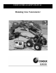
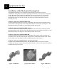
USER’S GUIDE & SAFETY MANUAL Running Line Tensiometer
Important Safety Notice WARNING: When using electric tools, basic safety precautions should always be followed to reduce the risk of fire, and personal injury, including the following: Read and understand all procedure and safety instructions before using the Condux Running Line Tensimeter. Observe all safety information on this page and note specific safety requirements as explained by procedures called out in this manual.
Table of Contents 1 General Information………………………………………. 4 2 Safe Operating Practices………………………………..5 3 4 5 6 Equipment Set Up……………………………………….. 9 Operating Instructions………………………………….. 16 Appendices………………………………………………….. 18 Rope Specifications………………………………………. 18 Calibration…………………………………………………… 18 Trouble Shooting Guide…..…………………………….19 Replacement Parts………………………………………..19 Warranty Information…………………………………….
1 General Information General Product Use A. The Condux Running Line Tensiometer, used with the Condux CableGlider® cable puller (or other rope capstan pullers) will give accurate measurements of the force exerted on a cable as it is installed. It consists of two components: the Mechanical Sensing Unit (which mounts directly to the cable puller) and the Electronic Control Box. !CAUTION: Electronic Control Box and Mechanical Sensing Unit are specifically calibrated as sets.
2 Safe Operating Practices Important Safety Instructions Electrical Requirement 1. This RLT should be grounded while in use to protect the operator from electric shock The RLT is equipped with a 3-conductor cord and 3-prong grounding type plug to fit the proper grounding type receptacle. The green conductor in the cord is the grounding wire. Never connect the green wire to a live terminal. If necessary, an adapter is available for connecting 3-prong plugs to 2-prong receptacles.
7. Do not use the RLT if the switches or buttons are malfunctioning. Have them replaced by an authorized service center. Disconnect Tools 8. Always disconnect the power when not in use and before installing, removing, or servicing the RLT. Keep Work Area Clean 9. Cluttered areas invite injuries. Consider Work Area Environment 10. Do not use the RLT in wet or damp locations, and do not expose it to rain 11. Keep the work area well-lit 12. Do not use the RLT in the presence of flammable liquids or gases.
Maintain RLT with Care 21. Follow instructions for changing accessories. Inspect the RLTs plugs regularly, and if damaged, have it replaced by an authorized service center. Inspect extension cords periodically, and if damaged, replace them. Keep the RLT dry, clean and free from oil and grease. Stay Alert 22. Watch what you are doing, Use common sense. Do not operate the RLT when you are tired. Check for Damaged Parts 23.
3. 4. DOWNGRADE OR DISCARD: When rope has been subjected to forces or conditions that reduce its strength, it should immediately be downgraded (used in less demanding or less critical applications) or discarded. It is both poor economics and unsafe to use rope beyond its normal lifetime. STAY CLEAR OF ROPE: Never allow anyone to stand in line with or within 30 degrees on either side of the rope under tension. WARNING: Rope under tension may break.
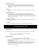
3 Equipment Set Up Installation of the Mechanical Sensing Unit The Mechanical Sensing Unit is designed to mount directly to the frame of Condux CableGlider® cable pullers. Two distinct mounting mechanisms are used for three cable puller models. Be aware of which model of CableGlider that your tensiometer is to be used with (CableGlider STD, HD, and Plus) and follow the specific instructions for the model.
Rope Installation !CAUTION: Running Line Tensiometer is not for use with steel cables of steel rope. Rope must follow a straight path over the cable puller sheaves and through the tensiometer. Avoid contact between rope and cable puller frame. Install rope without removing Mechanical Sensing Unit side plates or removing the sensing unit form the puller. Simply insert through the unit (See Figure 4). Arrows indicate direction of travel for inserting rope.
Figure 5 Figure 6 Power Connection Electrical power is supplied to the Electronic Control Box through the power cords located on the side of the unit. Located directly adjacent to the inlet is an outlet intended to supply power to the cable puller. Plug your puller into this outlet! The outlet can be programmed to stop the puller when an overload occurs or it can supply uninterrupted power. With power supplied to the inlet, the outlet is energized.
2. Select unit of measure pounds (Lb) or newtons (N). This must be done with no load on the RLT. On the RLT the display reads newtons and the chart recorder records in kilenewtons (See Figure 8) Figure 8 !DANGER: The Main Power switch supplies power to the indicator and chart recorder. When a power supply is connected to the electronic control box, portions of it are energized. Follow all electrical equipment precautions. 3. Set the cable Tension Limit.
Limiter switch is in the “ON” position the puller will stop pulling when the tension limit is reached (See Figure 10) Figure 10 Chart Recorder Set Up The Digital Chart Recorder is the next generation Solid State Data Recorder/Panel Recorder. This instrument has all the capability of a traditional paper recorder – variable chart speeds, the ability to review historic data, see trends and more. All pull data is stored on the 64MB Compact Flash Card that comes with the unit. 1.
Figure 12 Figure 13 Figure 14 14
2. Set to Record Mode: If you are already in the Record Mode screen, use the ▲ and ▼ buttons to scroll to “ON”. If you are starting from the charting screen, press “MENU” and scroll to Record Mode. Press “MENU” again to enter Record Mode, and scroll to ON. Push the “MENU” button to put a check mark next to “ON”. Your unit is now ready to record. The red light on the Chart Recorder panel should turn on when unit is recording. Press the ◄ or ► to return to the Menu screen.
4 Operation Instructions To Operate the Running Line Tensiometer Safely and efficiently, the user must have a working knowledge of the Condux CableGlider Puller. !WARNING: Read and Understand the “Cableglider User’s Guide and Safety Manual” before operating the CableGlider Cable Puller or Running Line Tensiometer. EQUIPMENT PREPARATION 1. Verify that the rope is properly inserted in the sheave grooves 2. Manually tension the rope. 3.
!CAUTION: Always wear protective equipment: hard hat, safety glasses, safety shoes, and work gloves. !WARNING : Stay clear of the rotating capstan. Severe personal injury or death could result from entanglement with it or the pull line. Follow these safety precautions. • Do not wrap the pull line around a hand, arm, foot, or leg. • Always be ready to release the pull line. 3.
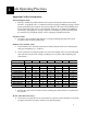
5 Appendices Recommended Working Load for Rope The recommended working load is determined by taking the average tensile strength of new rope under laboratory conditions, and dividing by a factor to determine the maximum load that should be applied to the rope. The factor varies with type of fiber and construction. This factor usually is sufficient to assure you of a comfortable safety margin, however, there are exceptions.
Troubleshooting Guide Problem: Digital display is not functioning Numbers on digital display start counting up and do not stop with no load on the rope. Cable puller does not stop when programmed tension limit is reached. Cable puller stops before line tension reaches preset load limit programmed into the Electronic Control Box. Solution: • Turn Electronic Control Box pwer switch ON • Check all electrical connections • Load cell is not properly connected to the electronic control box.
6 Warranty Information Condux International, Incorporated extends the following warranty to the original purchaser of these goods for use, subject to the qualifications indicated: Condux International, Incorporated warrants to the original purchaser for use that the goods or any component thereof manufactured by Condux International will be free from defects in workmanship for a period of 1 year form the date of purchase, provided such goods are installed, maintained, and used in accordance with Condux’s wr