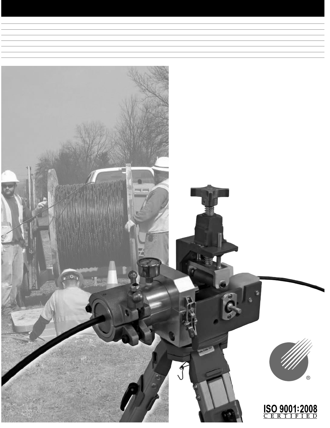
USER'S GUIDE & SAFETY MANUAL Mini-Blower/Pusher CONDUX
Important Safety Notice Read and understand all procedures and safety instructions before using the Mini-Blower/Pusher. Observe all safety information on this page and note specific safety requirements as explained by procedures in this manual. Failure to follow these instructions could result in serious personal injury or death. ADVERTENCIA: Favor de leer y comprender todas las instucciones de operación y seguridad antes de usar la máquina. Si Ud.
Table of Contents 1 2 3 4 5 6 7 General Information. . . . . . . . . . . . . . . . . . . . . . . . . . . . . . . . . . . . . . . . . . . . . . . . . . 4 Technical Specifications . . . . . . . . . . . . . . . . . . . . . . . . . . . . . . . . . . . . . . . . . . . . . . 5 A. Air Compressor Requirements. . . . . . . . . . . . . . . . . . . . . . . . . . . . . . . . . . . 5 B. Operational Capacities. . . . . . . . . . . . . . . . . . . . . . . . . . . . . . . . . . . . . . . . . 5 C.
1. General Information The operating instructions contain a full description of the Condux Mini-Blower/ Pusher, which has been designed for the purpose of feeding fiber optic cable through round conduits of uniform cross section. The conduit must previously have been installed underground or overhead to receive the fiber optic cable and must be of sufficient length on exit to be received by the machine.
OPERATOR QUALIFICATIONS a. Operator must know the required safety directives to run the machine that are pertinent to the country where it is being used. b. Operator in charge of the machine and installation project must be appropriately dressed, avoiding large clothes, hanging jewelry or whatever might become entangled in the moving parts. c. Operator must also wear the necessary protective equipment such as gloves, boots, helmet, etc. d.
3. Safe Operating Practices Read and understand all procedures and safety instructions before using the Condux Mini-Blower/Pusher. Observe all safety information on this page and note specific safety requirements as explained by procedures called out in this manual. Failure to follow these instructions could result in serious personal injury, property damage or death. A. WORK AREA SAFETY 1. Wear personal protective equipment: hard hat, safety glasses, safety shoes, and leather work gloves. 2.
Actual parts: 08081315 – blower assy 08081301 – pusher assy 08764110 – 12 mm duct pack 08764150 – 12.7 mm duct pack 08780302 – .23-.34 cable pack 08780304 – .35-.48 cable pack NOTE: If any parts are missing: please contact your Condux representative or call Condux International at 1-800-533-2077 (USA or CANADA), or 1-507-387-6576. Set Up the Blower/Pusher A. Mounting the Blower/Pusher to Tripod (Optional) NOTE: The Mini-Blower/Pusher can be operated without optional surveyor’s style tripod.
2. Once in place, secure the Blower Assembly to Drive Assembly using (2) #10-24 x 1 1/2" Capscrews. (See figure 3) 3. Select and install the appropriate sized Duct Clamp and Duct Seal to the Blower Assembly using (1) M04-0.7 x 16mm Capscrew for each. (See figure 4) Figure 3. Mount Blower Figure 4. Select & Install Duct Packs 4. Select and install the appropriate sized Venturi to the Blower Assembly using (1) M04-0.7 x 16mm Capscrew. (See figure 5) 5. Install the duct. (See figure 6) Figure 5.
6. Load cable through drive assembly. Select and install the appropriate size cable seals for the specific project. (See figure 7) 7. Install top venturi. (See figure 8) Figure 7. Select & Install Seals Figure 8. Install Top Venturi Blower/Pusher Operating Instructions A. Final Connections 1. Secure the blower assembly by closing the hinged top and tightening the blower clamp. (See figure 9) 2. Secure drive assembly by closing and locking the back clamp with locking clip. (See figure 10) Figure 9.
3. Adjust down pressure on cable by tightening the spring tensioned down pressure adjustment to ensure positive contact with drive roller. (See figure 11) 4. Connect the air hose to the blower utilizing the universal claw type connector. (See figure 12) Connect hose to air compressor follow specific manufacturer’s instructions. Figure 11. Adjust Pusher Down Pressure Figure 12. Connect Air !WARNING: Forced air creates flying debris. Always wear personal protective equipment.
2. Open air control valve to engage air pressure. (See figure 14) Important: Optimum air pressure not to exceed 40 PSI in microduct. 3. Engage drive system. Install fiber optic cable. (See figure 15) Figure 14. Engage Air Figure 15.
A. APPENDIX Blower/Pusher Charts MICRO DUCT PACKS Duct Size OD (MM) 10 12 12.
2 PACK REPLACEMENT CABLE PACKS CABLE PACK Cable OD P/N 1 0.23-0.34 (5.8-8.8) 2 30.35-0.60 (8.9-15.2) 3 4 VENTURI Cable OD 08780393 Pack #1 CABLE SEAL Cable OD 0.23-0.28 (5.8-7.2) 0.29-0.34 (7.3-8.8) 0.35-0.42 (8.9-10.7) 0.43-0.48 (10.8-12.2) 0.49-0.55 (12.3-14.0) 0.56-0.60 (14.1-15.2) 0.61-0.67 (15.3-17.0) 0.68-0.73 (17.1-18.5) 0.74-0.79 (18.6-20.1) 0.80-0.85 (20.2-21.6) 0.86-0.92 (21.7-23.4) 0.93-0.97 (23.5-24.6) 0.98-1.04 (24.7-26.4) 1.05-1.13 (26.5-28.7) P/N 0.23-0.34 (5.8-8.8) 08780281 0.
B.
DUCT ROD PUSHER (08081301) ITEM 1 2 3 4 5 6 7 8 9 10 11 12 13 14 15 16 17 18 19 20 21 22 23 24 PART NUMBER 02021400 02102001 02240800 02269675 02269678 02269687 02287830 02288425 02288443 02290269 08081302 08081305 08081319 08081308 08081309 08081310 08761033 08761034 08761036 08761045 08761510 08761516 12013700 21032451 DESCRIPTION QTY CAPSCREW, HEX HEAD 1/4-20 X 0.75LG GR5 CZ 2 FLATWASHER, 1/4 TYPE A NARROW CZ 7 CAPSCREW, BUTTON HEAD #10-24 X 0.50LG SS 4 CAPSCREW, BUTTON HEAD #08-32 X 0.
C. Blower/Pusher Assembly APPENDIX BLOWER/PUSHER ASSEMBLY (08780800) ITEM 1 2 3 16 PART NUMBER 02288338 08081301 08081315 DESCRIPTION CAPSCREW, #10-24 x 1.
Mini-Blower Assembly D. APPENDIX MINI-BLOWER ASSEMBLY (08081315) ITEM 1 2 3 4 5 6 7 8 9 10 11 12 13 14 15 16 17 18 PART NUMBER 00263400 02020000 02129700 02272600 02288582 02288665 02288694 02289293 02289294 02289295 02289297 02289382 08081316 08081317 08764001 08764006 08780223 11274400 DESCRIPTION CORD,QUAD-RING 3.5MM CS X 3.
E. Clamp Adjustment Screw APPENDIX CLAMP ADJUSTMENT SCREW ITEM 1 2 3 4 5 18 PART NUMBER 02102001 02287600 02288555 08761033 08761510 DESCRIPTION FLATWASHER, 1/4 TYPE A NARROW CZ FLATWASHER, 1/4 NYLON CAPSCREW, BUTTON HEAD 1/4-28 X 0.
Mount Clamp Assembly F. APPENDIX MOUNT CLAMP ASSY ITEM 1 2 3 4 PART NUMBER 02102001 02290268 08081311 08761510 DESCRIPTION FLATWASHER, 1/4 TYPE A NARROW CZ SCREW,SHOULDER 1/4 DIA X 3.25LG ROLLER,CLAMP ASSEMBLY MOUNT,CLAMP ROLLER Clamp Roller Assembly QTY 1 1 1 1 G.
Available Options Heavy Duty Tripod The Mini-Blower/Pusher mounts easily to the surveyor style tripod, which adds stability and versatility to fiber optic cable installations. Heavy Duty Tripod Part # 08780850 Pneumatic Drill Drive “Y” Connector A "Y" Connector air hose option allows for the use of a pneumatic drill drive configuration. Unit also comes with variable pressure control. "Y" Connector Air Hose Part # 08780855 Mini-Blower/Pusher job box The Mini-Blower/Pusher is easy to handle and transport.