USER’S GUIDE & SAFETY MANUAL Hand Held Micro Fiber Optic Blower
Important Safety Notice Read and understand all procedures and safety instructions before using a Condux Handheld Micro Fiber Optic Blower. Observe all safety information on this page and note specific safety requirements as explained by procedures in this manual. Failure to follow these instructions could result in serious personal injury or death. ADVERTENCIA Favor de leer y comprender todas las instucciones de operaciÓn y seguridad antes de usar la máquina. Si Ud.
Table of Contents 1. General Information………………………………………… Page 4 2. Set up the Handheld Blower………………………………… A. Pressure Test Conduit…………………………………… Page 5 Page 5-8 3. Prepare Conduits for Cable…………………………………. Page 9&10 4. Prepare Cable/Micro Cable…………………………………. A. Prepare Traditional Fiber Cable………………………… B. Prepare Micro Fiber Cable……………………………… Page 11 Page 11&12 Page 12&13 5. Handheld Blower Operating Instructions…………………… Page 14&15 6.
General Information General Product Use a. Only qualified operators should use this product. The operator should only be the person who received qualified training from the product owning company or trained by the manufacturer. b. Product must only be used for the work it was designed for. c. Product is not to be used with unauthorized personnel on the job site d. Should there be any doubt concerning use, functioning, maintenance or anything else, please contact the factory or factory representative.
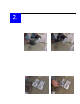
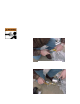
Set Up the Handheld Blower Pressure Test Conduit: The conduit system must be able to withstand a maximum pressure of 175 psi, and be free of leaks. Conduit may be tested for pressure using the Handheld cable blower, follow the steps below. 1. Loosen the speedball handle by turning it counter clockwise (Figure 1) until you are able to remove it from the bracket (Figure 2). Figure 1 Loosen speedball handle Figure 2 Remove speedball handle from bracket 2.
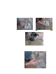
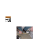
5. Choose the correct Venturi to fit the cable being installed. Do not install at this time! 6. Place the Seal Disk in Venturi Slot (See Figure 5). 7. Place conduit in the Conduit Seal and Conduit Clamp. Note placement up to ridge on Conduit Seal (See Figure 6). 8. Close Handheld Blower and secure (See Figure 7). Tighten speedball handle securely, but do not over tighten. Figure 5 Insert seal disk Figure 6 Insert duct Figure 7 Close and tighten handle 9.
10. Connect the Air Compressor a. Ensure Air Valve is off before connecting air hose. b. Attach the hose supplied with the air compressor to the air compressor coupling. The Handheld blower is equipped with a claw type connector. Use a safety clip on all pneumatic hose connections. (See Figure 9). c. Observe all safety procedures. d. Route all hoses properly to prevent tripping over them. !WARNING: Forced air creates flying debris. Always wear personnel protective equipment.
12. Prove conduit integrity. a. Close Air Control Valve by turning it to the 3 o’clock position (See Figure 11) b. Conduit must not lose more than 20 psi (1.38 bar) over a 2minute period. c. After 2 minutes, turn air compressor valve off leaving the blower pressure valve on until the air pressure gauge reads zero. d. If conduit fails to hold required pressure, check entire conduit run for leaks and repair them. e. Repeat the pressure test until all leaks are found and repaired.
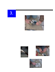
Prepare Conduit for Cable 1. Remove Conduit Pulling Eye from receiving end of Conduit. 2. Open Handheld Blower (See Figure 12) Figure 12 Open handheld blower 3. Pour recommended (silicon-based) lubricant into Conduit opening before Foam Carrier ¼ of the total recommend amount (See Figure 13) foam carriers are not provided with the Handheld blower. (See Page 19 for recommend amount of lubrication). 4. Insert foam into conduit (See Figure 14). 5. Insert Seal Disk in venturi slot if not already in place.
6. Close the Handheld Blower and secure (See Figure 16) Tighten speedball handle securely, but do not over tighten. 7. Prove Conduit integrity and spread lubricant through Conduit. a. Re-connect the air hose to the Handheld Blower and attach all safety clips. b. Open the air compressor air control valve. c. Slowly open Air Control Valve by turning to the 6 o’clock position. (See Figure 17) d. Blow foam through conduit to spread lubricant and check for blockage. Follow all safety precautions. e.
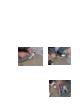
Prepare Cable/Microcable The Handheld Blower can be used to install traditional fiber cable or Micro Fiber Cable. Follow the steps below for the type of cable you will be installing. Prepare Traditional Fiber Cable: 1. Choose the correct Cable Grip and install on the fiber optic cable (See Figure 19). 2. Install 5/8” (16 mm) Swivel on Cable Grip using a 3/32” hex wrench. Grip must be firmly secured to cable (See Figure 20). The eye on the grip can be compressed to fit smaller diameter conduits.
7. Choose the correct Cable Seals and install on cable. Grooved side of Cable Seal faces the conduit. Place Cable Seals into the Venturi, split side down 8. Close the handheld blower and secure, Tighten speedball handle securely, but do not over tighten. Prepare Micro Fiber Cable The carriers are designed to attach to the central strength member (CSM) of the cable. The seals are sized to accommodate the proper ID duct size for maximization of blowing distances and create and air tight seal in the duct.
4. Slide two (2) Carrier Seals onto the CSM followed by two (2) Push Retainers. The seals should be relatively loose on the fiber but retained on the CSM with the Push Retainers. Note: Notice the direction of how the Push Retainers need to be assembled to the fiber. The cone portion of the retainer faces the end of the CSM. They should fit very tight onto the fiber. 5. Apply a tug on the Carrier Seals toward the end of the fiber to ensure the Push Retainers do not come off. 6.
Handheld Blower Operating Instructions 1. Station an observer with a 2-way communication device, at the far end of the Conduit, where the cable carrier will exit. 2. Re-connect hose from air compressor and attach all safety clips. Start the air compressor. Refer to respective manufacturers operating instructions for these units. 3. Slowly open the Air Control Valve to allow airflow to the Handheld Blower by turning the flow control valve hand to the 6 o’clock position. 4.
7. Open Handheld Blower and remove cable seals (See Figure 25). 8.
Handheld Blower Assembly Item No. 1 2 3 4 5 6 7 8 9 10 11 12 13 14 15 16 17 16 Part_Number Dwg_Description 00263400 02020000 02129700 02272600 02288582 02288665 02288694 02289293 02289294 02289295 02289297 02289382 08764001 08764003 08764004 08764006 11274400 QUAD-RING, 3.5MM-CS CORD 3.53" FTG,HYD 08-NPT_M ;08-NPT_M UNIVERSAL CPLG, 1/2 MALE FTG,HYD 08 O-RING;08-JIC 90 GAUGE,PRESS 0-200 1.50 BACK MT NUT M06-1.00 NYLOC ST GR2 CZ NUT M08-1.25 NYLOC ST GR2 CZ BOLT,SWING M10-1.
D uct Pack D u c t S iz e P /N D u c t C la m p D uct O D P /N D uct Seal D uct O D P /N C a rrie r D u c t ID P /N F o a m C a rrie r C a rrie r O D P /N C a b le G rip D uct O D P /N 1" S D R 1 1 /1 3 .5 08780386 Pack #1 1 .3 1 5 (3 3 .4 ) 08780369 B lu e 1 .3 1 5 (3 3 .4 ) 08780307 B lu e 1 .1 2 1 (2 8 .5 ) 08761811 1 .2 5 (3 1 .8 ) 08761439 1 .0 0 -1 .2 4 (2 5 .4 -3 1 .5 ) 08643137 0 3 3 -0 3 -0 1 3 1 .2 5 " S D R 1 1 /1 3 .5 08780392 Pack #2 1 .6 6 0 (4 2 .
C a b le P a c k C a b le O D P /N V e n tu r i C a b le O D 0 .2 3 - 0 .3 4 ( 5 .8 - 8 .8 ) 0 .2 3 - 0 .3 4 ( 5 .8 - 8 .8 ) 08780281 P u r p le 0 .3 5 - 0 .4 8 ( 8 .9 - 1 2 .2 ) 08780282 B lu e 0 .4 9 - 0 .6 0 ( 1 2 .3 - 1 5 .2 ) 08780283 Green 0 .6 1 - 0 .7 3 ( 1 5 .3 - 1 8 .5 ) 08780284 Red 0 .7 4 - 0 .8 5 ( 1 8 .6 - 2 1 .6 ) 08780285 G o ld 0 .8 6 - 0 .9 7 ( 2 1 .7 - 2 4 .6 ) 08780286 C le a r A lu m . 0 .9 8 - 1 .1 3 ( 2 4 .7 - 2 8 .7 ) 08780446 B la c k 08780393 Pa c k # 1 0 .
Recommended Blowing Lubricants Polywater® Prelube 2000™ Specially formulated for use with fiber optic cable blowing systems, Polywater® Prelube 2000™ has been field proven with the Deluxe LW Blower. This lubricant is a special lubricant used to prelubricate the conduit system before installing the cable. Prelube 2000™ is compatible with all types of cable jackets and conduit types. Part Number 08230600 08230601 08230900 08230901 Description 1 Quart (.9 liter) Squeeze Bottle 1 Gallon (3.
WARRANTY INFORMATION Condux International, Incorporated extends the following warranty to the original purchaser of these goods for use, subject to the qualifications indicated: Condux International, Incorporated warrants to the original purchaser for use that the goods or any component thereof manufactured by Condux International will be free from defects in workmanship for a period of 1 year form the date of purchase, provided such goods are installed, maintained, and used in accordance with Condux’s writ