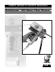
USER'S GUIDE & SAFETY MANUAL Gulfstream™ 200 Micro Fiber Blower
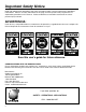
Important Safety Notice Read and understand all procedures and safety instructions before using the Gulfstream™ 200 Micro Fiber Blower. Observe all safety information on this page and note specific safety requirements as explained by procedures in this manual. Failure to follow these instructions could result in serious personal injury or death. ADVERTENCIA: Favor de leer y comprender todas las instucciones de operación y seguridad antes de usar la máquina. Si Ud.
Table of Contents 1 2 3 4 5 6 7 8 9 10 11 A General Information. . . . . . . . . . . . . . . . . . . . . . . . . . . . . . . . . . . . . . . . . . . . . . . . . . 4 Technical Specifications . . . . . . . . . . . . . . . . . . . . . . . . . . . . . . . . . . . . . . . . . . . . . . 5 A. Condition of Use. . . . . . . . . . . . . . . . . . . . . . . . . . . . . . . . . . . . . . . . . . . . . . 5 B. Air Compressor Requirements. . . . . . . . . . . . . . . . . . . . . . . . . . . . . . . . . . . 5 C.
1. General Information The Gulfstream™ 200 is a unique device for inserting fiber optic cable directly into conduit. The Gulfstream 200 is comprised of an air block and a tractor drive that, when combined with an air compressor and a battery pack, will propel fiber optic cable measuring 0.8mm to 5.5mm into an unobstructed, unoccupied, airtight conduit run at speeds of 0 to 165 ft/min (0-55 m/min). A cable carrier may be placed at the front end of the cable.
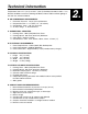
Technical Information a. Condition of Use: Temperature from 21° F (-6° C) to 110° F (+43° C) Humidity from 30% to 90% +/- 5%, Weather conditions relevant to working conditions, Natural and/or artificial lighting of the work site, minimum 200 lux. b. Air Compressor Requirements 1. 2. 3. 4. 2. Pneumatic Pressure: 175 psi (12 bar) Maximum Required Air Flow: 5 - 15 CFM (.14 - .42 m3/min) Conduit Size: 5mm – .50" (12.7mm) OD Air hose fittings: ¼" Quick Connect c. Operational Capacities 1. 2. 3. 4.
3. Safe Operating Practices Read and understand all procedures and safety instructions before using the Gulfstream 200. Observe all safety information on this page and note specific safety requirements as explained by procedures called out in this manual. Failure to follow these instructions could result in serious personal injury, property damage or death. a. Work area safety 1. Wear personal protective equipment: hard hat, safety glasses, safety shoes, and leather work gloves. 2.
Unpacking the Blower A. BLOWER COMPONENTS Each Gulfstream 200 STD Kit contains the following items: GS200 Micro Fiber Blower Battery Pack W/Cord Rechargeable Battery (2) Battery Charger Duct Clamp Insert Assemblies (5-7mm; 8.5-10mm; 12-12.7mm) Bottle of Lubricant Common Parts Kit (Includes: Cable Seals (1.5; 2.0; 2.5; 3.0; 3.5; 4.0; 4.5; 5.0; 5.5 mm) Blank Seal; O-Ring Kit; Seal Kit; Flat Belt; Hex Key Set; Plastic Case) 4.
5. Set Up the Blower This manual contains setup and operating instructions for the Gulfstream 200 micro fiber blower. A. DETERMINE FIBER SIZE Determine size of fiber to be installed. To provide optimal traction and grip, if fiber diameter is 1.5mm or less, the top belt of blower must be changed to a flat belt which is included in the common parts kit. This flat belt is to be used in combination with the bottom grooved belt, so that adequate contact and proper push force can be applied to the fiber.
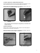
C. Install Cable Seal & Micro Fiber in Duct Pack Install the appropriate cable seal on the micro fiber. Make sure orientation of seal on fiber is correct so that it will seat in the duct pack properly. (See figure 1). Once the cable seal is positioned properly on the micro fiber, install the cable seal in the bottom half of the appropriate duct pack. (See figure 2). Figure 1. Install Micro Fiber in Cable Seal Figure 1.
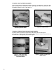
E. Install Duct & Fiber in Blower Loosen the knob on the Air Block assembly. Open the air block cover. Insert the duct pack assembly into the air block as shown. (See figure 5). Close air block cover and hand tighten knob to secure. (See figure 6). Figure 5. Insert Duct Pack Assembly into Air Block Figure 6. Tighten Knob F. Install Fiber in Tractor Drive and Tighten Feed the micro fiber between tractor drive and through the rear fiber guide. (See figure 7).
G. CONNECT BATTERY PACK TO BLOWER Attach power supply cable to blower unit and battery pack, tighten connections. (See figure 9). Once you have the supply cable connected, install the battery in battery pack as shown. (See figure 10). Figure 9. Attach Battery Pack Cable to Blower Unit Figure 10. Install Battery H. PANEL LAYOUT A description of each of the buttons and displays for the Gulfstream 200 micro fiber blower control box appears below. (See figure 11). Figure 11. Panel Layout Sel/Res: 1.
I. Connect Air Compressor NOTE: Ensure the air control valve is off before connecting the air hose. Attach the air compressor hose to the air compressor if necessary. Then connect the compressor hose to the blower unit. (See figure 12). The unit uses a standard quick connect air compressor coupling. Note: Route all hoses properly to prevent tripping over them. (See figure 12A). Figure 12. Connect Air Compressor Hose 12 Figure 12A.
Crash Test Cable Crash Testing is a very quick and easy step to be completed before attempting the installation of cable with the Gulfstream 200. This test is necessary to set the electronic push force control of the motor below the point that it may cause cable damage as a result of over pushing or encountering an obstruction in the sub-duct system. Every cable has different pushing values and these values vary depending on duct I.D. Example: A cable with a crash test value of 75 bar in 33 mm I.D.
7. Blower Operations A. Engage Air Start compressor. Slowly open the air control valve to allow air flow to the air block by turning the control valve knob clockwise. IMPORTANT: Do not exceed 175 PSI when operating the unit. !WARNING: Forced air creates flying debris. Always wear personal protective equipment. B. Verify adjustable push force Verify adjustable push force is set to the established crash test value and the speed is at minimum. C.
Tear Down Procedures !WARNING: Air Block Assembly contains compressed air when blower is operated. Opening Air Block while under pressure may cause serious personal injury. Ensure blower is depressurized before removing Air Block cover. A. Remove Power from Unit 1. Turn off compressed air by closing the Air Control Valve at the blower. (See figure 15). Shut off air at the compressor and decompress air hose. Depressurize the air block by turning the air control valve counterclockwise. (See figure 16).
9. Maintenance Procedure Daily Weekly Monthly 60 Days 90 Days Clean all assemblies and components thoroughly X X X X X Inspect fasteners and screws X X X X X Check Belt Tension. Replace if excess wear has occured X X X X X A. Track cleaning and tightening 1. Inspect track before and after each use. 2. Clean after each use, or when necessary.
2. Loosen tension screw on side of top assembly with allen wrench until the pulley can slide enough to free the belt (See figure 20). Figure 20. Loosen Tension Screw 3. Remove the belt (See figure 21). Figure 21. Remove the Belt 4. Install new belt. 5. Tighten tension screw on side of top assembly to 40 in-oz. 6. Repeat steps for bottom assembly (if required).
Troubleshooting Guide 10. Problem Cable becomes jammed in the conduit system. Solution 1. Inform the people at the other end of the conduit that a problem has been experienced and the operator is going to shut down the system. 2. Shut off the pneumatic air supply with the Air Control Valve turning it to the 9 o’clock position, allowing the air pressure to be depressurized from the conduit and the air block. 3.
Gulfstream 200 Replacement Parts 02290722 KNURLED THUMB KNOB(BRASS)-BELT CLAMP FORCE 02290724 MINI-GAUGE - 200PSI 02290725 MINI BALL VALVE 1/8NPT 02290727 3PIN CORDSET 02290834 KNURLED THUMB KNOB-DUCT CLAMP 08230675 POLY LUBRICANT 6PAC - 8OZ BOTTLE 08783026 BATTERY CLIP ASSEMBLY 08783065 KIT, BELT V-GROOVE GS200 (2 Belts) 08783070 KIT, BELT SMALL FIBER GS200 (1 Flat/1 V-Groove) 08783075 KIT, BELT FLAT GS200 (2 Belts) 08783051 DUCT CLAMP INSERT ASSY 5.0-7.
A.
ITEM 1 2 3 4 5 6 7 8 9 10 11 12 13 14 15 16 PART NO 02288203 02288240 02288636 02290723 02290724 02290725 02290726 02290739 02290740 02290749 02290834 08783020 08783025 08783032 08783034 08783035 DESCRIPTION CAPSCREW, #6-32X0.50 SHSTALY PL CAPSCREW, #6-32X0.37 BHSS 18-8 FITTING, HYD 02-NPT_M; 02-NPT_F 90 PLUNGER, SPRING #4-48 .1-.5# GAUGE, MINI 1/8 NPT 200 PSI VALVE, MINI 1/8 NPT BALL WEDGE COUPLING, QC 1/8 NPT 1/4 CPLG SCREW, SHOULDER .250 DIA-.875 SCREW, SHOULDER .188 DIA-.500 SCREW, SHOULDER .
4 5 21 13 2 9 20 15 10 11 3 6 8 14 16 17 9 20 19 11 7 1 18 3 12 5 15 10 22 22
ITEM 1 2 3 4 5 6 7 8 9 10 11 12 13 14 15 16 17 18 19 20 21 22 PART NO 02152600 02269674 02288269 02290722 02290728 02290729 02290738 02290742 02290743 08783065 08783070 08783075 08783081 08783004 08783082 08783006 08783008 08783009 08783010 08783011 08783018 08783030 08783079 12001302 DESCRIPTION CAPSCREW, #2-56X0.50 SHSTALY PL RING, RETAINING 0.250 EXTERNAL CAPSCREW, 0.25-20X1.25 SHSTALY PL KNOB, BRASS KNURLED, 1/4" SHAFT SPRING, COMPRESS .062-.500-.500 SPRING, COMPRESS .041-.360-.750 SPRING, COMPRESS .
Condux International, Inc. P.O. Box 247 • 145 Kingswood Drive, Mankato, MN 56002-0247 USA 1-507-387-6576 • 1-800-533-2077 • FAX 1-507-387-1442 www.condux.com • e-mail: cndxinfo@condux.com © Copyright 2013, Condux International, Inc. Printed in USA Literature Part Number: 08783049 Revision Number: 1.