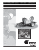
USER'S GUIDE & SAFETY MANUAL USER'S GUIDE & SAFETY MANUAL Fiber Optic Cable Puller Trailer
Important Safety Notice Read and understand these usage and safety instructions before using a Condux Fiber Optic Cable Puller Trailer. Observe all safety information on this page and note specific safety requirements as explained by procedures called out in this manual. Failure to follow these instructions could result in serious personal injury or death. Save this user’s guide for future reference.
Table of Contents 1. General Information 2. Product Specifications 3. Safe Operating Practices 4. Jobsite Floor Plan 5. Set Up The Trailer 6. Set up the Cable Puller 7. Set up the Electronic Control System 8. Operating the Power Unit 9. When the Cable Pull is Complete 10. Additional Takedown Procedures 11. Appendices Fiber Optic Cable Puller Trailer . . . . . . . . . . . . . . . . . . . . . . . . . . . . . . . . . . . . .4 General Dimensions . . . . . . . . . . . . . . . . . . . . . .
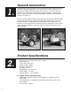
1. General Information Congratulations on your purchase of the Condux Fiber Optic Cable Puller Trailer. This unit is designed to provide a safe and efficient means to transport and operate the Condux Fiber Optic Cable Puller (figure 1). The trailer offers the platform for a self-contained cable pulling system including a hydraulic power source, cable puller mounts, leveling and stabilizing hardware, and a lockable storage area (figure 2).
C. HYDRAULIC SPECIFICATIONS Capacity: 8 gpm @ 2000 psi Reservoir capacity: 5 gallons Filtration: 10 micron nominal Oil Requirements: Petroleum based hydraulic oil with antiwear properties and high viscosities over 140 Relief Valve Setting: 2150 psi D. OTHER SPECIFICATIONS Electronics power requirements: 12 VDC Pulling Capacity: 1000 lbs with 30" dia. Condux capstan Towing Requirements: Class I hitch, 200 lbs.
C. ELECTRICAL COMPONENTS The Electronic Control Box is an electrical device. Electric shock hazard exists that could result in severe personal injury or death. Observe the following precautions to avoid electrical hazards: 1. Do not operate in or near water. This includes setting the Electronic Control Box on a wet surface or exposing it to rain. 2. Do not remove cover of Electronic Control Box. No user-serviceable parts inside. Refer servicing to qualified service personnel. 3.
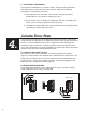
HAZARD AREA ECB FOOT CONTROL 20° OPERATOR Figure 4 C. POSITION THE TRAILER Position the trailer (in the position determined in 4A) with the tow vehicle. It is not recommended that any other means be used to move the trailer. Set Up The Trailer It is essential that the trailer set-up instructions are followed in order that they appear in this user guide and safety manual. Using the following procedures will allow the trailer to be set up in a short period of time and yield optimum performance. A.
2. Begin to stabilize the trailer by placing a wheel chock (2 supplied) behind each trailer wheel (figure 6). Figure 5 Figure 6 !WARNING: Load must be distributed evenly before unhitching trailer. Failure to do so may cause the trailer tongue to flip upward causing severe personal injury. 3. Remove trailer from tow vehicle. The trailer should be in position for cable pulling at this time (section 4).
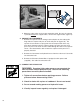
Set Up The Cable Puller A. FOR CABLE PULLING FROM TRAILER Move the cable puller from the travel position, if necessary, to achieve the best possible pulling position as determined in section 4. There are two steps to achieve this. 1. Change the placement of the cable puller on the trailer bed by inserting the puller into one of the two mounting holes on the side rails of the trailer frame. Note that the center (travel) position on the trailer bed already has its own mount.
Figure 11 Figure 12 5. Mount the cable puller on the remote mounting stand. Be sure the capstan is placed between the support tubes, not over the support tubes (figure 12). C. UNPACK THE COMPONENTS 1. Remove the capstan from its storage rack and place on the cable puller. Align slots on capstan with pins on shaft and push on (figure 10). The capstan sleeve contains a spring that must be compressed all the way, then rotate clockwise until the capstan springs into place over the shaft pins.
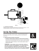
CABLE PULLER POWER SUPPLY PRESSURE FOOT CONTROL RETURN FACTORY CONNECTIONS QUICK COUPLERS Figure 13 Figure 14 The hydraulic system on your Condux Fiber Optic Puller Trailer allows easy, accurate connections of hydraulic hoses for the foot control and power supply (figure 13). All connect points must be kept clean! Use the following steps to connect your hydraulic components: 1. Connect the foot control to the power unit.
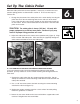
7. Set Up the Electronic Control System If the puller is not equipped with the electronic tension control system, go to section 8. A. SWITCH CONFIGURATION Following is a brief explanation of each of the switches for the Condux Fiber Optic Cable Puller Electronic Control System. Detailed instructions for using the equipment follows these explanations. Figure 15 1. Electronic Control Box Panel Switches (figure 15) Power: Turns control box ON or OFF.
• Do not expose electronic control box to water. • Do not remove cover of electronic control box (no user-serviceable parts inside). Refer servicing to qualified personnel. • The electronic control box power switch should be in the off position before connecting or disconnecting any cords. 1. Connect the male end of the 5-pin sensing cord to the female connector on the Electronic Control Box labeled “LOAD CELL”.
Tighten the connector collars over the threaded portion of the receptacles. This prevents the cord from coming loose during operation. This cord is necessary to measure the tensions sensed by the load cell. 3. The 7⁄8" 2-pin connector on the front panel of the electronic control box supplies electrical power to the electronic control box. (figure 16d) This power can come from the power pack, a vehicles power point, or a lighter socket.
4. Zero the display. Press the “Prog” button. 5. Alarms: When Tension Limiter switch is in the “OFF” position the audio alarm will sound and the light will come on when the tension limit is reached. When the Tension Limiter switch is in the “ON” position the puller will also stop pulling when the tension limit is reached (figure 5) !CAUTION: Damage to cable may result from excessive pulling forces. Use precautions to safeguard against overload conditions. D.
2. Set to Record Mode: If you are already in the Record Mode screen, use the ▲ and ▼ buttons to scroll to “ON”. If you are starting from the charting screen, press “MENU” and scroll to Record Mode. Press “MENU” again to enter Record Mode, and scroll to ON. Push the “MENU” button to put a check mark next to “ON”. Your unit is now ready to record. The red light on the Chart Recorder panel should turn on when unit is recording. Press the ◄ or ► to return to the Menu screen.
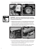
!DANGER: No smoking or open flame in the work area. An explosion hazard exists as the trailer houses a gasoline tank. B. FINAL INSPECTION BEFORE STARTING POWER UNIT 1. Inspect the jobsite for safe equipment layout. 2. Be sure the trailer is stable and level. 3. Supply all jobsite personnel with safety equipment (section 3). 4. Check engine oil level. See Briggs & Stratton Owner’s Manual (supplied). 5. Check hydraulic fluid level. 6. Check hydraulic connections. 7.
9. When The Cable Pull Is Complete A. STOP THE POWER UNIT 1. Turn throttle control to the slow position. 2. Turn the ignition switch for the power unit to the off position. !WARNING: Escaping fluids under pressure can penetrate the skin and cause serious personal injury. Observe the following precautions to avoid hydraulic hazards: 1. Relieve pressure before disconnecting hoses. 2. Check for leaks with a piece of cardboard. Do not use hands! B.
D. DISCONNECT THE ELECTRONICS !DANGER: The Electronic Control Box is an electrical device. Electric shock hazard exists that could result in severe personal injury or death. Observe the following precautions to avoid electrical hazards: 1. Do not remove cover of Electronic Control Box. No user serviceable parts inside. Refer servicing to qualified service personnel. 2. The Electronic Control Box power switch should be in the off position before connecting or disconnecting any cords. 1.
Figure 21 Figure 22 C. LOAD FOOT CONTROL UNIT Set foot control into travel hold on trailer bed (figure 22). Place hoses in storage box. D. PREPARE UNIT FOR TRANSPORT 1. Stow remaining equipment in compartment on trailer. A. APPENDIX Trailer Towing Safety Instructions !WARNING: Observe the following safety instructions when transporting the Condux Fiber Optic Cable Puller Trailer. Observe local, state, and federal laws governing trailer towing.
Routine Maintenance A. Clean and lubricate jack assemblies regularly to ensure ease of operation. B. Inspect tires for proper wear and always keep inflated to the specification denoted on the sidewall of the tire. C. Inspect lighting and replace bulbs as required. D. Follow the engine manufacturer’s maintenance schedule as described in the Briggs and Stratton Owners Manual (supplied). B. APPENDIX E. Follow proper care and maintenance of hydraulic systems.
Notes 22
Limited Warranty Condux International, Inc.
® Condux International, Inc. P.O. Box 247 • 145 Kingswood Drive, Mankato, MN 56002-0247 USA 1-507-387-6576 • 1-800-533-2077 • FAX 1-507-387-1442 Internet: http://www.condux.com © Copyright 2012, Condux International, Inc. Printed in USA Literature Part Number: 08675705 Revision Number: 1.