UVC1000/UVC1010 Table Top & Rack-mountable Pneumatic Vacuum Generator/Pressure Controller Operation and Maintenance Manual Condec Sales Phone Number: (888) 295-8475 Condec Web Site: www.4condec.
Contents About This Manual. . . . . . . . . . . . . . . . . . . . . . . . . . . . . . . . . . . . . . . . . . . . . . . . . . . . . . 1 1.0 Introduction . . . . . . . . . . . . . . . . . . . . . . . . . . . . . . . . . . . . . . . . . . . . . . . . . . . . . . 1 2.0 Operation . . . . . . . . . . . . . . . . . . . . . . . . . . . . . . . . . . . . . . . . . . . . . . . . . . . . . . . . 3 2.1 Input Air Pressure Supply. . . . . . . . . . . . . . . . . . . . . . . . . . . . . . . . . . . . . . . . . . . . .
About This Manual The UVC1000/UVC1010 is a rugged, compact instrument manufactured by Condec, designed to provide ease of operation, for the calibration of a wide variety of pressure sensing and measuring devices. Equipped to perform rapid on-site calibrations, these instruments have proven to substantially reduce the cost, system down-time and man-hours of labor normally associated with these routine service functions.
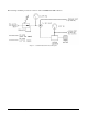
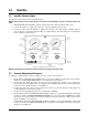
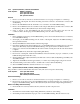
The following schematic provides an overview of the UVC1000/UVC1010’s function. Figure 1-1.
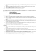
2.0 2.1 Operation Input Air Pressure Supply See Figure 2-1 below and proceed as described below. NOTE: The air pressure source used must have a vent valve and be regulated to provide a maximum output of 160 PSIG. 1. Pull PRESSURE LIMIT CONTROL (1) knob outward and rotate counter-clockwise until it stops. 2. Connect the input hose, supplied by customer, to a clean regulated shop air source. 3.
3.0 3.1 Maintenance Troubleshooting Symptom Problem Remedy Pressure Limit Monitor gauge or Vacuum Leak in system Monitor gauge slowly decreases over time Check all compression and pipe fittings with soap solution or Snoop® (PN 64781) Applicable gauge does not respond No regulator control when Pressure Limit Control knob is turned Try other mode of operation. If o.k, replace gauge, otherwise replace Pressure Limit Control regulator Table 3-1. UVC1000/UVC1010 Troubleshooting 3.
UVC1000 Cover Installation: 1. Vent input line pressure. 2. Pull out the PRESSURE LIMIT CONTROL knob, until you hear a click. Close regulator, rotate knob counter-clockwise, until it stops. Push knob inward. 3. Replace and align cover. 4. Install and tighten the six screws (PN 14839) that secure the cover to the enclosure. 5. Replace input hose, if not previously attached. UVC1010 Cover Removal: 1. Vent input line pressure and remove input and port hoses. 2.
3.2.4 Vacuum Monitor (PN 59230) and Pressure Limit Monitor (PN 59706) Gauges - Removal and Installation Tools required: 7/16" wrench 9/16" wrench A/R 1/4" wide Teflon tape (PN 60575) Removal: 1. 2. 3. 4. Remove cover from its enclosure as described in Section 3.2.2 on page 4, and place on a bench top. Disconnect the tubing section that connects to the gauge fitting. Loosen the two thumb-nuts that hold the gauge mounting U-clamp.
3.2.6 Input Port (PN 59761) - Removal and Installation Tools required: Phillips screwdriver 7/16" open end wrench 9/16" open end wrench 5/8" open end wrench Removal: 1. Remove cover from its enclosure as described in Section 3.2.2 on page 4, and place on a bench top. 2. From inside of back panel, disconnect the tubing section that connects to the male tube connector (PN 57705) fitting. 3. Remove the AN bulkhead end nut and ferrules, note orientation, from AN bulkhead fitting. 4.
3. Slide fractional tube adapter fitting into input port AN bulkhead fitting (PN 59761), from inside of rear panel. 4. Tighten the AN bulkhead end nut approximately 1-1 /4 turns beyond finger tight, using 9/16" wrench. 5. Test UVC1000/UVC1010 as described in Section 3.2.1 on page 4. 3.2.8 Vacuum Generator (PN 57960) - Removal, Cleaning and Installation The vacuum generator is a Venturi device which creates a vacuum flow by use of a regulated air flow.
4.0 Specifications Models: Pressure Hose Fittings: UVC1000 (PN 56085): Table Top Unit UVC1010 (PN 59415): 19” Rack Mount Unit Quantity Supplied: Style: Operating Temperature:+40° to +110°F (+4.4° to +43.3° C) Storage Temperature: 0° to +185° F (–17.8° to +85°C) Pressure Media: Filtered shop air Pressure Limit Monitor Gage: Enclosure: Size: Range: Type: Material thickness: Finish: 2-in.
UVC1000/UVC1010 Warranty and Return Policy If possible, please save original packing material which is specifically designed for the unit. Should it be necessary to ship the unit back to the factory, a suitable shipping container must be used along with sufficient packing material. Do not put a shipping label on the unit as a "suitable shipping container." Some units have been severely damaged this way. This is a delicate, precision instrument.
UVC1000/UVC1010 Return Material Authorization Form The repair lab is also equipped to do calibrations on our calibrators and pressure standards. Calibrations include a certification and are traceable to N.I.S.T.