
Instruction Manual


28 UPS3000/UPS3110/UPS3210 Operation and Maintenance Manual
4.0 Maintenance & Service
4.1 Troubleshooting
4.2 Maintenance & Service Procedures
This section outlines the mechanical and BASIC electrical repair procedures for the portable pneumatic pressure
calibrator, model UPS3000/UPS3110/UPS3210. The repair procedures cover the major components and
sub-assemblies which are critical to the proper functioning of the calibrators and that will likely need periodic
maintenance over the life of the unit. Only those persons who are formally trained as skilled technicians should
attempt to repair these units. All relevant safety precautions should be observed due to the presence of electrical
components and high-pressure.
4.2.1 Case Removal and Installation
UPS3000 External Case Removal/Installation
NOTE: Verify pressure has been vented from system prior to case removal. Although not recommended the instrument
may be fully operated with the case removed without any potentially lethal shock hazard to operating personnel, since
accessible internal voltage is nominally 25 VDC.
1. Loosen the two thumbscrews (PN 68916) located at the bottom outermost corners of the front panel.
Screws will remain captivated to front panel but will allow chassis to slide away from rear of case.
2. Use screws to slide front panel/chassis away from case.
3. If all power and pressure connections have been removed. Gently slide panel/chassis out until back edge
of panel/chassis touches lip on front of case.
4. Tilt front of panel/chassis upward slightly and remove from case. Place assembly on a bench top.
Reverse procedure for installation.
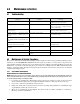
Symptom Problem Remedy
Display not lit Unit will not energize Check fuse, check power source, if
applicable check power switch
Display slowly decreases over time Leak in system Check all compression and pipe fittings
with snoop, bottle of liquid leak gas
detector (PN 64781)
Display does not respond when Vernier
knob is turned
No Vernier control Readjust isolation valves on Orion;
replace O-ring on Vernier piston
Display increases or decreases when
INPUT (Pressure) or VENT valves are
closed
No pressure or vent control Replace valve seats or O-rings in valves;
check valve needles
Unit will not stay in CAL, display shows
"O", display reads a high value @ zero
PSIG
Transducer over-pressurized Replace transducer
Low battery indicator on display
illuminates when unit is powered
Low or no battery power Re-charge battery, check power supply
charging voltage
No display when in battery mode after
charging
Battery will not hold charge Replace battery
Display will not zero Perform a ZERO/SPAN calibration
Display will shift, will not be steady Transducer drifts or possible over
pressure
Replace transducer
Table 4-1. UPS3000/UPS3110/UPS3210 Troubleshooting