
Instruction Manual

Calibration and Adjustment Procedure 25
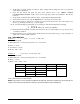
Example 2:
If the current barometric pressure is above 14.70 PSIA, subtract the current barometric pressure from 14.70.
14.70 PSI: UPS3110 reference point
-14.75 PSI: Current barometric pressure
-.05 PSI: Negative Delta Offset
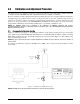
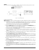
Figure 3-6. Vacuum Pump Setup
Complete the following steps:
NOTE: UPS3000 refer to Figure 2-1 on page 5 and Figure 2-4 on page 6. UPS3210 refer to Figure 2-3 on page 6 and
Figure 2-6 on page 8.
1. Connect Vacuum Test Standard to UPS3000/UPS3210 Input Port similar to Figure 3-6. A vacuum pump
will need to be connected such that the Vacuum Test Standard controls the output coming from the
vacuum pump going into the
INPUT PRESSURE port (16) of the UPS3000/UPS3210.
2. Open the vent valve connected between Test Standard and UPS3000/UPS3210.
3. Using the RANGE SELECT switch (6), select the lowest pressure range on the UPS3000/UPS3210.
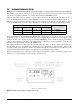
4. Press the ENTER push-button, as shown in Figure 3-2 on page 20, on the UPS3000/UPS3210. The
display reads zero. Repeat this step for the middle and high ranges.
5. Close the vent valve connected between Vacuum Test Standard and UPS3000/UPS3210. Select the
lowest pressure range of the UPS3000/UPS3210.
6. Turn the vacuum pump on creating a vacuum. Using the Vacuum Test Standard to control the vacuum
until the UPS3000/UPS3210 display reads the value of the Negative Delta Pressure, -0.05 PSI as in this
example.
7. Depress the ENTER push-button on the UPS3110. The display reads zero. Without touching the Vacuum
Test Standard settings repeat this step for the middle and high ranges.
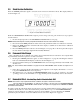
8. Using the STEPPER push-button, as shown in Figure 3-2 on page 20, place the unit into SHUNT RESISTOR
CALIBRATION mode. The display will be as shown in Figure 3-5 on page 23.
9. With UPS3000/UPS3210 RANGE SELECT switch (6) switched in the high range, depress the ZERO
push-button on the front panel. Verify that the display reads 0.00. Upon release of the push-button the
display will be as shown in
Figure 3-5 on page 23.
10. Depress the ENTER push-button. The display will respond with “[] [] [] [] [] []” until the button is
released.
11. Pressing the STEPPER push-button bring the indicator back to its initial Data Recall display condition as
shown in
Figure 3-2 on page 20. The display shows 1 XXX (three arbitrary digits).
12. Depress the DATA ENTER switch, S2, located approximately in the middle of the circuit board. See Figure
2-7 for the switch location
13. If the data is accepted, the three-digit number on the right side of the display will indicate 377 for as long
as the
DATA ENTER switch, S2, is depressed.
14. The barometric offset is now complete and CALIBRATE/OPERATE switch, S3, must be returned to its
normal operating positions as shown in
Table 3-1 on page 20. The Vacuum Test Standard may now be
disconnected.