
Instruction Manual

22 UPS3000/UPS3110/UPS3210 Operation and Maintenance Manual
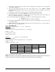
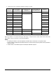
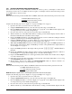
2. Perform the action as indicated when the readings are stable.
When step number 11 is reached, the display will change so that the left most status symbol will be “H”. This
will remain for step 12 and down to approximately 0.00 psi.
NOTES:
1. If reading is in motion or correction required is not within ±0.8% of Full-Scale, no entry will be made.
2. If entry is valid, the display will momentarily indicate the correction value (in percent) and the memory location at
which it is stored.
3. If 100% ±0.05% is not obtained, repeat the Zero/Span calibration sequence.
STEP NO.
INPUT PRESSURE,
% OF RANGE
OPERATOR ACTION
REQUIRED
STATUS SYMBOL IN
LEFT MOST DIGIT
REMARKS
1 0 Press ZERO Switch “Upper Circle” Zero on Display
2 10 Press ENTER Switch Notes 1 & 2
3 20 Notes 1 & 2
4 30 Notes 1 & 2
5 40 Notes 1 & 2
6 50 Notes 1 & 2
7 60 Notes 1 & 2
8 70 Notes 1 & 2
9 80 Notes 1 & 2
10 90 Notes 1 & 2
11 100 No Action Required “Lower Circle” Note 3
12 50 Press ENTER Switch Notes 1 & 2
13 0 No Action Required “L”
Table 3-3. LINEARIZATION & HYSTERESIS CALIBRATION SEQUENCE