
Instruction Manual

Calibration and Adjustment Procedure 21
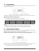
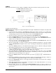
3.3 Zero/Span Calibration
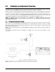
Pressing the STEPPER push-button switch once places the instrument into its ZERO/SPAN calibration mode. The
display will be shown in
Figure 3-3.
Figure 3-3. Zero/Span Calibration for Gage Only Units (Each Range)
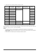
Starting with the instrument’s lowest pressure range, sequentially perform steps 1 and 2 shown in Table 3-2 for
each pressure range. Perform the following for each step.
NOTE: Perform Step 1 in all ranges prior to doing Step 2.
1. Adjust input pressure to the appropriate (either 0 or 100%) value.
2. Perform the action indicated by the table when pressure input readings are stable.
NOTES:
1. If readings are not stable or are not within ± 20% of zero, the zero correction cannot be entered.
2. If readings are not stable or are not within ± 5% of 100%, the span correction cannot be entered.
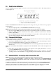
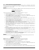
3.4 Linearity and Hysteresis Calibration
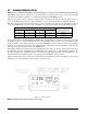
The unit can be placed in LINEARIZATION/HYSTERESIS mode by pressing the STEPPER push-button under the
middle of the display as shown in
Figure 3-2. The display is shown in Figure 3-4.
NOTE: The zero/span calibration needs to be performed prior to linearity and hysteresis calibration. For Absolute Only
Unit, vacuum pump with PSIA indicator must be used to obtain readings below local barometric pressure.
Figure 3-4. Linearity and Hysteresis Calibration
Starting with the instrument's lowest pressure range, sequentially perform the thirteen steps described in
Table 3-3 on page 22, for each pressure range being calibrated. Perform the following for each step.
1. Adjust input pressure to the appropriate value without overshooting the setting.
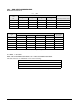
Step Number Pressure Input Valve Operator Action Required Resulting Display Indication Remarks
1 0% Press ENTER Switch 0% Note 1
2 100% Press ENTER Switch 100% Note 2
Table 3-2. Zero and Span Calibration Sequence