
Instruction Manual

20 UPS3000/UPS3110/UPS3210 Operation and Maintenance Manual
3.2 Instrument Calibration Set-Up
NOTE: See“Case Removal and Installation” on page 28 and Figure 2-7 on page 8 to locate DIP switch S3 on CPU board.
UPS3000 is placed into its calibrate mode by momentarily opening instrument drawer and setting the DIP
switch, S3 in accordance with
Table 3-1. Connect Test Standard to UPS3000 Input Port.
UPS3110, disconnect the input pressure and power lines and remove the unit from its rack. Remove the top
cover. Set the DIP switch, S3 in accordance with
Table 3-1 and connect Test Standard to UPS3110 Test Port.
UPS3210, disconnect the input pressure and power lines and remove the unit from its rack. Remove the top
cover. Set the DIP switch, S3 in accordance with
Table 3-1 and connect Test Standard to UPS3210 Input Port.
In the CALIBRATE mode the UPS3000/UPS3110/UPS3210’s digital displays are used to provide the operator with
prompting symbols, as well as displaying the various data formats employed. The front panel button switch,
under the middle of the display, becomes a sequential
STEPPER key used to select the various programming
functions (Zero/Span, Linearity/Hysteresis, Shunt Resister Calibration) and the push-button (CAL) directly
beneath the conversion display is used as the
ENTER switch.
All calibration functions will be performed in PSI engineering units, as “Gauge” (atmospheric reference)
measurements, unless the instrument being calibrated has been configured as an “Absolute Only” unit. If so, the
procedures in this section should be followed, except that an absolute (0 psia) reference must be utilized. A good
2-stage vacuum pump should be employed to attain greater than 100 microns Hg. vacuum.
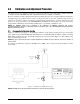
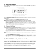
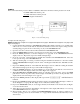
Figure 3-2 depicts the location of the above described front panel switches as well as showing the display format
obtained as soon as the unit has been placed in the CALIBRATE mode.
Figure 3-2. Calibration Keys
NOTE: UPS3000 shown Input Port located on back of unit.
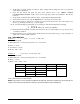
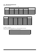
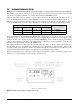
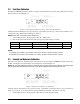
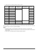
Switch Settings S3
Program Switch ModePosition 1 Position 2 Position 3 Position 4
0 0 0 0 Operate
1 0 1 0 Calibrate
Table 3-1. CALIBRATE/OPERATE Switch Settings