
Instruction Manual


Operation 15
2.8.2 UPS3110 Pressure Measurement Sequence Absolute (ABS) Mode
NOTE: If local barometric pressure is not 14.7, ABS/GAGE switch selectable units only, may need barometric offset. See
“Barometric Offset - Absolute/Gage Switch Selectable Units ONLY” on page 23.
1. If only pressure measurements greater than barometric are required, continue to step 1.1. If pressure
measurements above and below atmospheric pressure are required go to step 2.
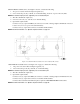
To apply pressure, close the VENT valve (12), approximately two turns, until it stops, then open the INPUT
valve (10) approximately 1/2 turn counter-clockwise until the numerical display begins to move. The
pressure may change rapidly until reaching approximately 90% of the desired final value.
1.1. Use either the INPUT (10) or VENT valve (12) to obtain a specific pressure reading. Both provide
precise control. As the pressure approaches the desired value, the valve being used for control should
be rotated slowly clockwise to its closed position. With a little experience, pressure values very close
to the desired final value may be quickly achieved.
1.2. To obtain exact pressure readings, slowly rotate the VERNIER control (11) knob in the direction
required (clockwise to increase pressure) as indicated by the electronic numerical display
Application of pressures greater than 1.5 times the highest pressure range of the indicator may cause
calibration errors or even permanent damage to the pressure transducer.
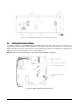
2. If pressure measurements above and below atmospheric pressure are required, connect a VACUUM
PUMP to the VACUUM/VENT port (19).
3. Open the VENT valve (12), close the INPUT valve (10) and apply power to the vacuum pump and allow it
to evacuate the system for several minutes or until the digital display reading reaches equilibrium near
Zero psia. Press the
ZERO push-button switch (1) to establish a zero reference on the display.
4. With the vacuum pump still running, close the VENT valve (12) (approximately two turns to its stop) and
check for system leaks. If there are none, continue to step 4.1.
4.1. To apply pressure, open the INPUT valve (10) (approximately 1/2 turn counter-clockwise until the
numerical display begins to move). In general, the pressure may be changed rapidly until reaching
approximately 90% of it desired final value.
4.2. Use either the INPUT (10) or VENT (12) valve to obtain a specific pressure reading. Both provide
precise control. As the pressure approaches the desired value, the valve being used for control should
be rotated slowly clockwise to its closed position. With a little experience, pressure values very close
to the desired final value may be quickly achieved.
4.3. To obtain exact pressure readings, slowly rotate the VERNIER control (11) knob in the direction
required (clockwise to increase pressure) as indicated by the electronic numerical display.
2.9 GAGE Mode Self-Check
For UPS3000, refer to Figure 2-1 on page 5 and Figure 2-4 on page 6.
For UPS3110, refer to Figure 2-2 on page 5 and Figure 2-5 on page 7.
For UPS3210, refer to Figure 2-3 on page 6 and Figure 2-6 on page 8.
NOTE: Use of this Self -Check is not required for the proper operation of unit. CAL key is non-functional in absolute
mode due to the inability to simulate a perfect vacuum reference.
1. Vent the Input Pressure port (16) to atmosphere.
2. Momentarily depress the ZERO push-button switch (1). The display will indicate 0.00.
3. Momentarily depress the CAL push-button switch (5). The display will immediately blank except for two
“- -” which indicate that the unit is performing the self-check. If the self-check is successful, the display
will flash “
100.00” and revert to its normal zero indication.
#AUTION