
Instruction Manual


14 UPS3000/UPS3110/UPS3210 Operation & Maintenance Manual
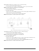
2.8 UPS3110 Initial Setup Sequence
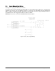
Refer to Figure 2-2 on page 5 and Figure 2-5 on page 7.
1. Connect the pressure source to the instrument via the INPUT PRESSURE port (16), 7/16-20, 37
o
-4 AN male
fitting provided on the rear panel. It is suggested that a Cheat Seal, PN 54854, be used between INPUT
PRESSURE
port and pressure source fitting.
2. Check that the INPUT valve (10) is closed (rotate clockwise until it stops) and that the VENT valve (12) is
open (two turns counter-clockwise from its stop).
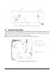
3. Plug in the power cord (17) and energize the unit by pushing the POWER switch located on front panel.
Allow at least 10 minutes warm-up time.
4. Select the desired full scale pressure range via the three-position rotary RANGE SELECT switch (6). For
the best accuracy, the selected range must be greater than, but close as possible to, the full scale range of
the Device-Under-Test (DUT).
NOTE: Do not switch pressure ranges during a calibration cycle.
5. Using the PRESSURE LIMIT CONTROL regulator (7), adjust the maximum system input pressure, as read by
the
PRESSURE LIMIT MONITOR (8), to any desired value higher (typically 20–50% higher) than the
full-scale range of the DUT. Using this technique, the DUT is fully protected from being accidentally
over-pressurized.
NOTE: UPS3110 []A[] and UPS3110 []G[] units do not have PRESSURE LIMIT CONTROL or MONITOR.
6. Connect the male end of the test hose to the TEST PORT (9) fitting.
7. Connect the swivel fitting end (7/16-20) of the Test (output) hose to the DUT using adapters if required.
Tighten all connections properly.
8. If applicable or required, select the mode of operation by momentarily depressing the ABS/GAGE (2)
switch. The applicable “ABS” or “GAGE” light bar (4) will be lit to provide mode of operation.
9. To select the desired measurement display units, depress CONV (3) switch.
NOTE: When the PEAK HOLD or MAX/MIN option is supplied with a model having the ABS or GAGE mode, switch
selectable from front panel, the “CONV” button will be disabled and will not be present on the front panel. Refer to
Section 2.6 on page 12.
10. If operating the unit in GAGE mode go to Section 2.8.1 or if operating the unit in ABS mode go to
Section 2.8.2.
2.8.1 UPS3110 Pressure Measurement Sequence GAGE Mode
1. Press the ZERO push-button switch (1), display will return to a normal “Zero” reading. The instrument
may be zeroed at anytime, as long as the
VENT valve (12) is open, by momentarily depressing the ZERO
push-button switch (1).
2. To apply pressure, close the VENT valve (12), approximately two turns, until it stops, then open the INPUT
valve (10) approximately 1/2 turn counter-clockwise until the numerical display begins to move. The
pressure may change rapidly until reaching approximately 90% of the desired final value.
3. Use either the INPUT (10) or VENT valve (12) to obtain a specific pressure reading. Both provide precise
control. As the pressure approaches the desired value, the valve being used for control should be rotated
slowly clockwise to its closed position. With a little experience, pressure values very close to the desired
final value may be quickly achieved.
4. To obtain exact pressure readings, slowly rotate the VERNIER control (11) knob in the direction required
(clockwise to increase pressure) as indicated by the electronic numerical display.
Application of pressures greater than 1.5 times the highest pressure range of the indicator may cause
calibration errors or even permanent damage to the pressure transducer.
#AUTION