
Instruction Manual


Operation 7
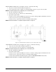
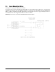
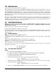
UPS3110 Rack-mountable Series, See Figure 2-5 below, contains the following:
1. AC power cord, fuse holder and input receptacle (17).
2. INPUT PRESSURE port (16), 7/16-20, 37
o
-4 AN male fitting. Location of port for AC only units.
NOTE: The maximum input pressure, supplied by user, is noted below port.
3. The unit’s identification plate (15).
4. VENT/VACUUM PORT (19), 7/16-20, 37
o
-4 AN male fitting.
5. Optional if required items:
Connector J1 (14), 5 pin round MS style connector, for Serial or Analog Output communication board or
location of Input Pressure port for models with battery.
Connector J2 (18), 5 pin round connector, for the Freeze Mode Cable.
NOTE: For further information, see “Options, Replacement Kits” on page 54.
Figure 2-5. UPS3110 Rack-mountable Pressure Calibrator Rear View
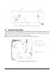
UPS3210 Rack-mountable Series, See Figure 2-6 on page 8, contains the following:
1. AC power cord, fuse holder and input receptacle (17).
2. INPUT PRESSURE port J3 (16), 7/16-20, 37
o
-4 AN male fitting.
NOTE: The maximum input pressure, supplied by user, is noted above port.
3. The unit’s identification plate (15).
4. Optional if required items:
Connector J1 (14), 5 pin round MS style connector, for Serial or Analog Output communication board.
Connector J2 (18), 5 pin round connector, for the Freeze Mode Cable.
Co n n e ct o r J 4, l o c a t e d b e l o w i d en ti f ic a ti on p la t e , re q ui re d fo r A P C4 0 0 0 /A P C 4 00 1 in te r fa c e c a b l e.
NOTE: For further information, see “Options, Replacement Kits” on page 54.