
Manual

Maintenance and Service 19
4.2.8 ORION-2D Manifold - Panel Installation
Tools required: 7/16" open end wrench
Phillips screwdriver
hex wrench (.061")
snoop, liquid leak gas detector (PN 64781)
11/32" open end wrench (thin)
1. If not already done, remove the panel knobs from the COARSE (pressure), VERNIER, and VENT valves
using the .061" hex wrench.
2. Install the manifold with the transducer port side facing the panel bottom. Install the two mounting
screws (PN 60837) from the panel front and tighten until snug.
NOTE: Some manufactured units may have the vacuum generator mounted to the ORION-2D manifold body. If so, install
the muffler, coupling and long nipple assembly into the vacuum generator.
3. Install the VERNIER knob (17) onto the VERNIER valve shaft (14). Align the set screws (25) with the
indentations on the vernier valve shaft and tighten until snug using the .061" hex wrench.
4. To install and adjust the
COARSE (pressure) and VENT valve knobs, follow the procedure in
Section 4.2.9.
5. Install the transducer into the manifold port, tighten with the 11/32" thin wrench and reconnect its wire
connector.
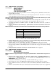
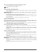
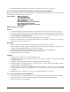
NOTE: If transducer is hard-wired, connect the four wires to the terminal block TB1 on the CPU board per Table 4-2.
6. Install the flexible tubing going to the transducer port. Also the flexible tubing coming from the vacuum
generator, compressed air port, and the mode select assembly.
7. Install the tubing section from the
VENT outlet fitting on the ORION-2D, using a 7/16" wrench.
8. Fill the cylinder to approximately 1000 PSIG and check all fittings for leaks. If there are no leaks, fill
nitrogen supply cylinder to maximum pressure. See Section 2.1 on page 4 for cylinder refilling
procedure.
9. Install panel/chassis assembly in its enclosure as described in Table 4.2.1 on page 14.
4.2.9 ORION-2D Manifold - Valve Adjustment Procedure
Tools required: hex wrench (.050")
hex wrench (.061")
snoop, leak gas detector (PN 64781)
NOTE: See Table 4-6 on page 33 and Figure 4-1 on page 34 for parts information. * denotes reference to Figure 2-2 on
page 5.
1. Energize the unit and let it warm up, 10 to 15 minutes minimum. Rotate the SUPPLY SELECT valve to
the N
2
position, the RANGE SELECT switch to the 100 PSI range, DISPLAY SELECT switch and the
MODE SELECT valve to pressure position.
2. To adjust the
COARSE valve, go to next step. To adjust the VENT valve, go to step 18.
3. If not already done, remove the ORION-2D
COARSE valve knob (3) using the .061" hex wrench
4. Using a .050" hex wrench, loosen the set screw (34) on the locknut (2) and turn the locknut clockwise to
its stop.
5. Check to see that the knob insert (4) is securely fastened to the valve shaft (11). If it is loose, tighten the
Transducer Wires Terminal Block Wires
+ Excitation TB1-4 (Green wire)
- Signal TB1-6 (Red wire)
+ Signal TB1-5 (White wire)
- Excitation TB1-7 (Black wire)
Table 4-2. Transducer Wire to Terminal Block Wire Connections