
Manual

12 UPC5100/UPC5110 Operation & Maintenance Manual
When Step 11 is reached, the display changes so that the left most status symbol is a lower circle. This remains
for Step 12 and down to approximately 0.00 PSI.
NOTES:
1. If reading is in motion or correction required is not within ±0.8% of full-scale, no entry is made.
2. If entry is valid, the display momentarily indicates the correction value (in percent) and the memory location at which it is
stored.
3. If 100% (±0.05%) is not obtained, repeat the zero/span calibration sequence.
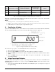
3.5 Shunt Resistor Calibration
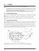
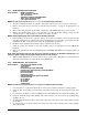
To place the UPC5100/UPC5110 into shunt calibration mode, install the Condec Calibration Module (PN 60109)
and select the SHUNT MODE position of the rotary switch. The display is shown in Figure 3-4.
Figure 3-4. Display in Shunt Resistor Calibration Mode.
Perform the four step sequence on the UPC5100/UPC5110 as described below.
1. Be sure the input pressure is set at 0 PSIG.
2. Press and hold the
ZERO button on the module until a stable zero indication is obtained.
3. Release the
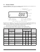
ZERO button and allow the display to stabilize at its shunt resistor calibration number (100 ±
5.00%).
4. Press the
ENTER button on the module. When accepted, the bottom half of all display digits
momentarily illuminate.
3.6 Voltage/Current Input Calibration
To calibrate unit, a current generator capable of generating 20 mA, must be connected to the COMMON and
CURRENT INPUT jacks (Figure 2-3 on page 7 [14]). The DISPLAY SELECT switch (16) should be in the
VOLTAGE position.
1. Set the Condec Calibration Module (PN 60109) to the
ZERO/SPAN position (see Figure 3-2 on page 10
for display reading).
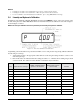
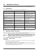
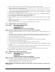
11 100 No Action Required Lower Circle Note 3 below
12 50 Press ENTER button Lower Circle Notes 1 & 2 below
13 0 No Action Required Upper Circle
Step Input Pressure % of Range
CONDEC Calibration Module
Operator Action Required
UPC5100/UPC5110
Display Status Symbol in
Left-most Digit
Remarks
Table 3-2. Linearization and Hysteresis Calibration Sequence (Continued)