
Manual

Calibration 11
NOTES:
1. If readings are not stable or are not within ±20% of zero, the zero correction can’t be entered.
2. If readings are not stable or are not within ±5% of 100%, the span correction cannot be entered.
3. For ease of calibration, do the Linearity/Hysteresis calibration , prior to doing ZERO/SPAN of next range.
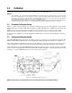
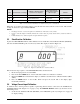
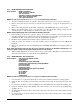
3.4 Linearity and Hysteresis Calibration
Install the Condec Calibration Module (PN 60109) and select the LYN/HYS position of the rotary switch on the
module. This places the UPC5100/UPC5110 into its linearization/hysteresis calibration mode. The display is
shown in Figure 3-3 below.
NOTE: The zero/span calibration needs to be performed prior to linearity and hysteresis calibration.
Figure 3-3. Linearity and Hysteresis Calibration
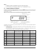
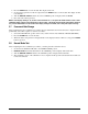
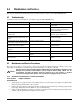
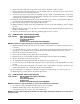
Sequentially perform the thirteen steps described in Table 3-2, for each pressure range being calibrated. Perform
the following for each step:
1. Adjust input pressure to the appropriate value without overshooting the setting. If value is overshot, vent
unit and repeat steps.
2. Perform the action as indicated when the readings are stable, 1 to 2 minutes. If it is taking longer, check
system for leaks. If no leaks are found, the CPU or transducer may be defective.
Step Input Pressure % of Range
CONDEC Calibration Module
Operator Action Required
UPC5100/UPC5110
Display Status Symbol in
Left-most Digit
Remarks
10 Press ZERO switch Upper Circle Zero on display
210Press ENTER button Upper Circle Notes 1 & 2 below
320Press ENTER button Upper Circle Notes 1 & 2 below
430Press ENTER button Upper Circle Notes 1 & 2 below
540Press ENTER button Upper Circle Notes 1 & 2 below
650Press ENTER button Upper Circle Notes 1 & 2 below
760Press ENTER button Upper Circle Notes 1 & 2 below
870Press ENTER button Upper Circle Notes 1 & 2 below
980Press ENTER button Upper Circle Notes 1 & 2 below
10 90 Press ENTER button Upper Circle Notes 1 & 2 below
Table 3-2. Linearization and Hysteresis Calibration Sequence