UPC5100/UPC5110 Portable & Rack-mountable Pneumatic Pressure Calibration Console Operation & Maintenance Manual CONDEC Sales Phone No. (888) 295-8475 CONDEC Web Site: www.4condec.
Contents About This Manual ................................................................................................................................... 1 1.0 Introduction.................................................................................................................................. 1 2.0 Operation...................................................................................................................................... 4 2.1 2.2 2.3 2.4 2.5 2.6 3.
5.0 Model Number System .............................................................................................................. 36 6.0 Available Ranges, Conversions and Resolutions ...................................................................... 37 7.0 Options - Replacement Kits ....................................................................................................... 38 8.0 Specifications .............................................................................................
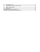
About This Manual This manual is intended for use by service technicians responsible for installing and servicing the UPC5100/UPC5110 pneumatic pressure console. The UPC5100 portable pneumatic pressure calibrator and the rack-mounted UPC5110 are rugged, compact instruments manufactured by Condec. They are designed to provide superior accuracy, range of calibration and ease of operation when used for the calibration of a wide variety of pressure sensing and measuring devices.
• System Calibration: The instruments can be completely calibrated without being removed from the external case. A separate plug-in Condec Calibration Module (PN 60109) provides access to the computer when calibration is performed. No manual alignment or potentiometer adjustments are required. • Calibration Integrity: Once calibrated, the tamper-proof design provides numerous safeguards that guarantee the integrity of pressure readings obtained.
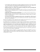
The following schematic provides an overview of the UPC5100/UPC5110’s function. Figure 1-1.
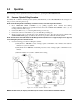
2.0 Operation The following sections explain the various procedures for operating the UPC5100/UPC5110. 2.1 Pressure Cylinder Filling Procedure To initially fill or refill the internal pressure cylinder (2015 PSI max) of the UPC5100/UPC5110, see Figure 2-1 and proceed by following these steps: NOTE: Check the Nitrogen Fill Port markings on Pressure Console, some units may be 2216 PSI max. 1. Close PRESSURE LIMIT CONTROL (1) by pulling regulator knob outward and turning counter-clockwise.
2.2 Shop Air Operation 1. Turn the SUPPLY SELECT valve (7) to the SHOP AIR position and connect a shop air hose to the male fill port (4). Maximum input pressure is 150 PSI. 2.3 Initial Setup Procedure To prepare for actual calibration usage, see Figure 2-2 below and proceed as follows: 1. Check that the COARSE ADJUSTMENT valve (2) is closed (rotate clockwise until it stops) and that the VENT valve (8) is open (two turns counter-clockwise from its stop). 2.
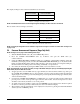
The display scaling for these current measurements are as follows: SWITCH POSITION DISPLAY READING Current 0-20.000 mA by 0.005 mA *Voltage 0-100.00 mV by 0.02 mV Table 2-1. Display Select Switch (16) NOTE: UPC5100/UPC5110 reads a 4-20 mA signal only, but will display as either 4-20 mA or 20-100 mV. The test cable connector wiring is as follows: CONNECTOR PIN DESIGNATION FUNCTION A + VDC B + SIGNAL C NOT USED D VOLTAGE & SIGNAL COMMON Table 2-2.
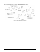
Figure 2-3. Pressure or Vacuum Measurement Sequence NOTE: UPC5100 shown, AC Input (7) and Fill Port (4) are on back side of UPC5110 Rack Mountable Calibrator. 2.5 Vacuum Measurement Sequence See Figure 2-3 above and proceed as follows: 1. 2. 3. 4. Turn the MODE SELECT valve (10) to the VACUUM position. Close the COARSE ADJUSTMENT valve (2) clockwise and open the VENT valve (8), counter-clockwise. Zero the unit by pressing the ZERO button (12).
7. With the vacuum pump still running, close the VENT valve (8) and check for system leaks. If there are none, continue to step 7.1 2.6 7.1 To apply pressure, close the VENT valve (8) (approximately two turns to its stop) and open the COARSE ADJUSTMENT valve (2) (approximately 1/2 turn counter-clockwise until the numerical display begins to move). In general, the pressure may be changed rapidly until reaching approximately 90% of its desired final value. 7.
3.0 Calibration Follow the procedure on the following pages for calibrating the UPC5100/UPC5110. NOTES: • • 3.1 When calibrating, the computer within the UPC5100/UPC5110 is actually being re-programmed, therefore it is important that the pressure standard being used is in satisfactory operating condition and that the technician fully understands its operating characteristics and methods of usage.
3.3 Zero/Span Calibration Selecting the ZERO/SPAN position on the Condec Calibration Module (PN 60109) places the instrument into its ZERO/SPAN calibration mode. The display is shown in Figure 3-2. Figure 3-2. Zero/Span calibration for Gage-Only Units The unit needs to be calibrated to only one positive and one bi-directional range. All bi-directional ranges are calibrated over 0 to +14 PSI and 0 to -14 PSI. All the positive ranges from 0 to 100 PSI.
NOTES: 1. 2. 3. 3.4 If readings are not stable or are not within ±20% of zero, the zero correction can’t be entered. If readings are not stable or are not within ±5% of 100%, the span correction cannot be entered. For ease of calibration, do the Linearity/Hysteresis calibration , prior to doing ZERO/SPAN of next range. Linearity and Hysteresis Calibration Install the Condec Calibration Module (PN 60109) and select the LYN/HYS position of the rotary switch on the module.
Input Pressure % of Range CONDEC Calibration Module Operator Action Required UPC5100/UPC5110 Display Status Symbol in Left-most Digit 11 100 No Action Required Lower Circle Note 3 below 12 50 Press ENTER button Lower Circle Notes 1 & 2 below 13 0 No Action Required Upper Circle Step Remarks Table 3-2. Linearization and Hysteresis Calibration Sequence (Continued) When Step 11 is reached, the display changes so that the left most status symbol is a lower circle.
2. Press the ENTER button on the module. The display reads 0.00. 3. Set the current generator for 20 mA output. Press the ENTER button on the module. The display should read 100.000. 4. Turn the DISPLAY SELECT switch (16) to the CURRENT position. Display will read 20.000. 5. Disconnect the current generator. NOTE: If the display reading is off, set the Current Generator to 0, and press the ENTER button on the Condec Calibration Module. Set the Current Generator for 20 mA output. The display will read 20.
4.0 Maintenance and Service This section outlines the mechanical and basic electrical repair procedures for the UPC5100/UPC5110. 4.1 Troubleshooting Use Table 4-1 below for information on troubleshooting the UPC5100/UPC5110.
UPC5100 Installation: 1. Lift the panel and chassis by first grasping the fill port fitting and test port. 2. Gently place panel/chassis assembly into enclosure. Ensure that the wire harnesses do not catch and snag. 3. Align mounting holes and install the eight screws (PN 14862) that secure the panel assembly to the enclosure. UPC5110 Removal: 1. Verify that power toggle switch is in the OFF position.
4.2.3 ORION-2D Manifold Removal (PN 55286) Tools required: Phillips screwdriver 11/32" wrench or nutdriver .061" hex wrench adjusting screwdriver (small flat blade) 11/32" open end wrench (thin) 7/16" open end wrench NOTE: See Table 4-6 on page 33 and Figure 4-1 on page 34 for additional parts information. 1. Vent any remaining nitrogen from cylinder to atmosphere. Disconnect power cord from power source. 2. Remove front panel from its enclosure as described in Section 4.2.
7. Remove the valve stem seats (8) and valve needle seats (9) using the needle-nose pliers. 8. Remove the inner and outer O-rings (28, 27) and back-up rings (31, 30) from the valve stem seats and wash all parts in solvent (de-natured alcohol). 9. To remove valve seats (7) from either the COARSE (pressure), VENT, or ISOLATION valves, try blowing compressed air through the inlet and outlet fittings. Otherwise, the center holes will have to be drilled and a tap used to extract the seat (Steps 10-13). 10.
4. Apply a small amount of fluorinated Krytox grease to the shaft threads and install the shaft (14) into the end cap. 5. Install the end bushing (12) and tighten until snug using the isolation valve needle housing socket (PN 68509) and socket wrench. 6. Feel vertical motion of shaft (14). If motion exists, remove end bushing (12) and add a thicker washer at Step 3, otherwise continue to Step 7. 7.
4.2.8 ORION-2D Manifold - Panel Installation Tools required: 7/16" open end wrench Phillips screwdriver hex wrench (.061") snoop, liquid leak gas detector (PN 64781) 11/32" open end wrench (thin) 1. If not already done, remove the panel knobs from the COARSE (pressure), VERNIER, and VENT valves using the .061" hex wrench. 2. Install the manifold with the transducer port side facing the panel bottom. Install the two mounting screws (PN 60837) from the panel front and tighten until snug.
6. 7. 8. 9. 10. 11. 12. 13. 14. 15. set screws (23) with the .061" hex wrench. Close the COARSE valve by turning the knob insert (4) clockwise until you feel the valve needle seat on the O-ring (valve is now in the closed position). Rotate gear (6) on the ISOLATION valve (inner valve), counter-clockwise until stopped, then rotate clockwise 1/2 turn (opening isolation valves). Use the PRESSURE LIMIT CONTROL (*1), to increase the supply pressure to between 80% and 100% of full scale.
4.2.10 Chassis Mounted Regulator (PN 55502) - Removal, Installation and Adjustment Tools required: channel locks adjustable wrench flat blade screwdriver (small) 7/16" open end wrench 9/16 " open end wrench hex wrench (1/4") A/R 1/4" wide Teflon tape, (PN 60575) A/R 1/2" wide Teflon tape, (PN 60911) snoop, liquid leak gas detector (PN 64781) 1/2" socket socket wrench plug fitting (PN 69199) Removal: 1. Vent any remaining nitrogen from cylinder to atmosphere. Disconnect power cord from power source. 2.
4. Remove end of nylon tubing that goes to the SUPPLY SELECT assembly, other end stays connected to vacuum control assembly. Install customer supplied nylon tube, with fitting on other end, into SUPPLY SELECT assembly. Install fitting end into test port of customer supplied Standard 5. Remove section of copper tubing that goes from Chassis Mounted Regulator to cylinder tee fitting. Tighten plug fitting (PN 69199) where copper tubing section was on regulator. 6.
4.2.12 Supply Pressure (PN 59730) and Pressure Limit Monitor (PN 59706) Gauges - Removal and Installation Tools required: 7/16" wrench 9/16 " wrench A/R 1/4" wide Teflon tape (PN 60575) snoop, liquid leak gas detector (PN 64781) Removal: 1. Vent any remaining nitrogen from cylinder to atmosphere. Disconnect power cord from power source. 2. Remove front panel from its enclosure as described in Section 4.2.1 on page 14, and carefully place on a bench top. 3.
4. Fill the cylinder to approximately 1000 PSIG and check all fittings for leaks. If there are no leaks fill nitrogen supply cylinder to maximum pressure. See Section 2.1 on page 4 for cylinder refilling procedure. 5. Install panel/chassis assembly in its enclosure as described in Section 4.2.1 on page 14. 4.2.14 Test Port Filter (PN 54188) - Removal, Cleaning and Installation The port filter is a sintered element filter that can be easily removed for inspection and cleaning.
NOTE: Some vacuum generators are mounted with screws and nuts or adhesive. 5. Clean the vacuum generator by using compressed air. Warning Do not use solvent for cleaning. Removal and Cleaning - Aluminum Body (PN 54965) 1. Remove ORION-2D manifold from front panel as described in Section 4.2.3 on page 16, and carefully place on a bench top. NOTE: Remove the muffler and long nipple from the vacuum generator’s exhaust port prior to removing the two manifold mounting screws. 2.
4.2.16 Vacuum Control Regulater (PN 59765) - Removal, Installation and Adjustment The vacuum control regulator is located furthest from front panel on the chassis. Some vacuum control regulators have a locking screw in place of pulling knob outward. Tools required: 7/16" open end wrench hex wrench (.186") adjustable wrench channel locks Phillips screwdriver A/R 1/4" wide Teflon tape, (PN's 60575) snoop, liquid leak gas detector (PN 64781) Removal: 1. 2. 3. 4. 5. 6.
11. Install panel/chassis assembly in its enclosure as described in Section 4.2.1 on page 14 4.2.17 Inlet Check Valve, Nitrogen Fill Port (PN 60263) - Removal, Disassembly and Installation Remove the check valve if it does not hold the pressure of the N2 cylinder. The check valve can be disassembled for cleaning should any debris foul the seat area.
4.2.19 AC Power/EMI Line Filter (PN 58870) - Removal and Installation Tools required: Phillips screwdriver 1/4" open end wrench or nutdriver A/R soldering iron A/R shrink sleeving (PN 60735) A/R heat gun 1. Disconnect the power cord from the power source and line filter. Remove front panel from its enclosure as described in Table 4.2.1 on page 14, and carefully set on a bench top. 2. Remove the three cable connectors from the line filter terminals.
4.2.21 Power Switch (PN 58878) for Non-Battery Units - Removal and Installation Tools required: Phillips screwdriver 11/16" open end wrench A/R soldering iron A/R shrink sleeving (PN 64567) A/R heat gun Removal: 1. Disconnect the power cord from the power source and line filter. Remove front panel from its enclosure as described in Section 4.2.1 on page 14, and carefully set on a bench top. 2. Loosen the switch mounting nut and lock washer from the rear of panel. 3.
Installation: 1. Connect and solder the wires onto their respective switch terminals (Table 4-4). Range Select: Display Select: Pole - Terminal Color Pole - Terminal Color 1-3 Yellow 2-2 Red 1 - 6 (common) Red 2-3 Blue 2-3 Orange 2 - 6 (common) Green 3-4 Brown Table 4-4. Range Select and Display Select Wire Colors/Switch Terminals 2. 3. 4. 5. Install the switch through the panel rear, align with front panel markings, and secure with mounting nut. Install the switch knob using a .
4.2.24 Power Supply Assembly (Battery Units Only) - Removal and Installation 120 VAC input (PN 58727); 220 VAC input (PN 58733). Tools required: Phillips screwdriver Flat blade screwdriver (small) 11/32" open end wrench or nutdriver Removal: 1. Disconnect the power cord from the power source and line filter. Remove front panel from its enclosure, as described in Section 4.2.1 on page 14, and carefully set on a bench top. 2.
5. Unplug the power cord from the power source. 6. Disconnect the voltmeter and reconnect the battery leads to the battery terminals; red wire to (+) and black wire to (-). 7. Install panel/chassis assembly in its enclosure as described in Section 4.2.1 on page 14.
4.
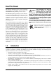
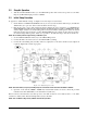
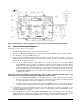
38 16 THESE COMPONENTS TO BE INSTALLED AT LOCATIONS A & C 10 1 B 2 33 25/2X C 34 7 23/2X 9 4 28 3 1 40/2X 43/2X 24/3X 3 4 31 15 27 35/2X 1 20 30 3 32 8 1 12 3 41 OR 21/6X 5 42 4 7 14 A 1 27 9 1 28 39 1 26/2X 31 3 42 27 1 2 3 4 1 LIGHTLY COAT THE FOLLOWING WITH LUBRICANT (PN 55593): O-RINGS, ITEMS 27, 28, 29 & 32. THREADS ON VALVE NEEDLES, ITEMS 11 & 18. ITEMS 41 & 42 QUANTITY AND USAGE TO BE SELECTED DEPENDENT ON FIT, SEE VERNIER CONTROL REASSEMBLY IN MANUAL.
Figure 4-2. Range Select Switch Wiring Figure 4-3. Display Select Switch Wiring Figure 4-4.
5.
6.0 Available Ranges, Conversions and Resolutions NOTE: Non-standard ranges are available by special order. Calibrator Conversion Factors: • kPa = PSI x 6.89476 • Bar = PSI x 0.0689476 • mBar = PSI x 68.9476 • Torr = PSI x 51.7149 • mm Hg = PSI x 51.7149 • in Hg (0˚F) = PSI x 2.036 • • Kg/cm2 = PSI x 0.070308 in H2O (60˚F) = PSI x 27.71 • cm H2O = PSI x 70.308 NOTE: Display resolution 0.02% of selected range, unless it is not devisable by 1, 2, or 5. RANGES RESOLUTION +-28.000 in Hg / +-387.
7.0 Options - Replacement Kits There are numerous replacement PN’s mentioned through out manual that can be ordered. ORION-2D O-Ring Replacement Kit (Data Sheet # 65308): • Nitrile Buna-N (standard) - PN 58499 • Ethylene-Propylene - PN 58506 • Silicone - PN 58509 • • Neoprene - PN 58515 Fluorocarbon “Viton” - PN 55277 Note: A small coating of Fluorinated Krytox grease, (PN 55593), should be applied to both sides of O-ring prior to installation.
8.0 Specifications Pressure Specifications: Fill Port: Pressure ranges: Style: Pressure Rating: +- 0-28 in Hg +- 0-387.00 in H2O + 0-2771.0 in H2O +- 0-96.00 kPa + 0-100.00 PSI Available Pressure Calibrations: Test Port: Pressure Rating: Gage and Vacuum gage and absolute Overall Accuracy: < ±0.05% Full Scale Max. Accuracy statement includes all effects of linearity, hysteresis, repeatability and ambient temperature Operating Temperature: +40° to +122°F (+4.4° to +50.
Carrying Case UPC5100 only: Physical Specifications: Type: UPC5100 Weight: 34 lbs. including all hoses and cables UPC5110 Weight: 36 lbs. UPC5100 Case Dim’s: 10" wide x 16" long x 11.5" high UPC5110 Case Dim’s: 19" wide x 8.1" deep x 10.5" high (Case dimensions excluding front handles) Material Thickness: Finish: Color: Aluminum case with latched cover and handle 0.090 in., nominal Enamel paint, textured finish Gray Control Panel: Material: Thickness: Finish: 40 Aluminum (5052-H32) 0.
REVISIONS REV REFERENCE AF ECO10483: DELETED ITEMS 10 & 11; REDRAWN ON RLW FORMAT AG DELETED ITEM NUMBER 2 . ECO11898: ADDED NOTE 27, ADDED INFO TO ITEM NO. 101 ON AH LIST OF MAT'L, ADDED INFO TO ITEM 31, ADDED NOTE 28 AND 29, REMOVED SPEC. FROM ITEM 61, 62, 65 AND 1 THRU 54 28- KEU8924-1 (54254) & KEU8924-3 (54263) ONLY: ON CIRCUIT SIDE OF BOARD, CUT CLAD BETWEEN CR12 ANODE AND VIA UNDER U10. CUT CLAD BETWEEN CR10 ANODE AND U6-4. ADD 3 1/2" 30 AWG WIRE, ITEM 101, BETWEEN CR10 ANODE AND VIA UNDER U10.
Figure 8-2.
Figure 8-3.
REVISIONS REFERENCE REV W THRU AB INIT SEE C/N'S FOR CHG. DESCRIPTIONS W-C/N D2858, Y-C/N D2900, AA-C/N D2948, AB-C/N D2968. AC AD AE AF AG AH AJ C/N D3121; IT. 95 QTY WAS 11 1/2 IN. C/N D3710, ITEM 10 WAS KBF8918B; IT. 24 WAS RN55010ROF; IT. 57 WAS KLY3118; IT. 95 WAS M16878/4BGBO. C/N D4003 L/M: ITEM 53 PART# WAS: KJE3118; DESC. WAS CAPACITOR, MYLAR. QTY OF ITEM 96 WAS: -1=0; -2=1 1/2"; -3=0; -4=1 1/2" ; ADD'D NOTE 27; UPDT'D SHT. 2. DELETED ITEMS 2, 10, AND 11.
Figure 8-5.
Figure 8-6.
Figure 8-7.
Figure 8-8.
Figure 8-9.
Figure 8-10.
UPC5100/UPC5110 Warranty and Return Policy If possible, please save original packing material which is specifically designed for the unit. Should it be necessary to ship the unit back to the factory, a suitable shipping container must be used along with sufficient packing material. Do not put a shipping label on the unit as a shipping container. Some units have been severely damaged this way. This is a delicate, precision instrument.
UPC5100/UPC5110 Return Material Authorization Form The repair lab is also equipped to do calibrations on our calibrators and pressure standards. Calibrations include a certification and are traceable to N.I.S.T.